Ford Modular Boss with RBT ZF in a 40 install notes

Hi All,
I looked for information on this combination but didn't find much. Mostly I found or was given information that almost changed my mind about this motor.
So for those who are interested I will share my information here and update it as I can.
I also will try to keep the mechanical seperated from the electrical.
Feel free to help out if I am missing something.
Hopefully this will help others!
 

Attachments

  • IMAG0218.jpg
    IMAG0218.jpg
    298.5 KB · Views: 734
Mechanical
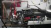
Zf transaxle, Ford Boss modular motor, and a KEP bell housing.
11 inch pressure plate will not clear the inside bolt flange to transaxle with out chamfering the edge of the KEP bellhousing. This would have been great for a CNC but went with a Dewalt flap disc. To maintain clearence all fitment was done with out the steel motor plate in place, this will increase clearence and hopefully guarantee no grinding when motor starts. If this remains an issue I will have a 11inch pressure plate and disc for sale!
The top two bolts from the bell housing to the transaxle will need to be counter sunk Allen bolts as the pressure plate interference issue, a 10.5 inch pressure plate might fix this issue.
The ZF requires a 12 mm ID and 19mm OD pilot bearing so a bushing will be made to fill void between 19mm OD and crank ID. still working on this the last cut in the lathe was a slip fit. gotta make another one now!
By measuring what I have the pilot bearing will need to be inserted 3/16 further than flush mount.
Made a small grind on the block and on starter case. This allowed the starter to rotate motor down. This will require a smaller hole in chassis and lower center of gravity.
Alternator with driver side mount required a notch in chassis. The altenator that mounts above water pump would not require this mod.
Intake manifold was reversed for back of motor or throttle body would protrude into cockpit.
Remove the roll cage and fire wall before attempting to install motor and transaxle combination this will keep you from asking "what was that" when a bang occurs.
No special input shaft for the transaxle or spacers used so far.
 
Electrical

Most of the ford factory wiring harness gets unwrapped, rearranged and rewrapped. I have a special tool to push the tab in on the water tight connectors this will allow the wires to be untangled and rewrapped with minimal splicing

The motor harness will reach the passenger side battery box this is where I will place the ECU, I would have preferred the left side but do not want to splice 4 feet of wire to the main motor wire harness and auxiliary motor harness. A plastic tab holdind the harness to the valve cover had to be removed, it made contact with fire wall.

The cable from the ECU to the cockpit will reach to the underside of the dash. I routed it thru the right sponsen above the gas tank so it is hidden and out of the way!:thumbsup:

The TPS will need to be lengthen as the throttle body is now a back of motor location. I'm thinking I can get a section from the junk yard so their will only be one splice.

The Starter wire looks good

The MAF is yet to be determined

The cooling fan and ground wire for same was removed from the factory harness as it start location is the Power Distribution Box (it was going to the rear of the car). The PDB is now under the dash by the right door hindge mount.

So far only one wire has been cut and spliced in the ford harness. it needed about 6 inches added to move Y in the harness closer to the ECU.
 
Back
Top