Calling all engineers…..after some advice please!
Having finally found the time to fit some brackets I’ve had made to raise the inboard mounting point of the top link,( many thanks to Howard for his help), I now have a few questions…..
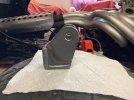
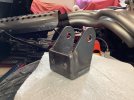
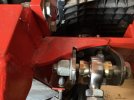
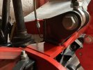
1. Brackets - these are made from 4mm steel and raise the top link inboard mounting point by 40mm level with the webbing. They fit in exactly the same place as the original brackets with just a small slot needed in the webbing. Is this strong enough from an engineering point of view?
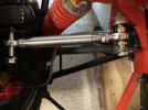
2. New top link spacers - 1/2” rod ends with steel ‘misalignment spacers’ each side. I need to make additional spacers to fill the remaining gaps…what material should be used - does it need to be steel or is aluminium ok….grades?
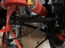
3. Top link orientation ( warning, this could be a silly question!)….does it matter where this is placed within the bracket or should it be inline with the lower reverse A arm?…the reason I ask is that on the GTD the lower arm and top link are spaced with washers to change rear toe…I have all the washers on the front lower arm and had the same on the old top link….do I need to somehow replicate this?
Hopefully I can upload some photos.
Thanks in advance.
Cheers
Dave
Having finally found the time to fit some brackets I’ve had made to raise the inboard mounting point of the top link,( many thanks to Howard for his help), I now have a few questions…..
1. Brackets - these are made from 4mm steel and raise the top link inboard mounting point by 40mm level with the webbing. They fit in exactly the same place as the original brackets with just a small slot needed in the webbing. Is this strong enough from an engineering point of view?
2. New top link spacers - 1/2” rod ends with steel ‘misalignment spacers’ each side. I need to make additional spacers to fill the remaining gaps…what material should be used - does it need to be steel or is aluminium ok….grades?
3. Top link orientation ( warning, this could be a silly question!)….does it matter where this is placed within the bracket or should it be inline with the lower reverse A arm?…the reason I ask is that on the GTD the lower arm and top link are spaced with washers to change rear toe…I have all the washers on the front lower arm and had the same on the old top link….do I need to somehow replicate this?
Hopefully I can upload some photos.
Thanks in advance.
Cheers
Dave