Improving the SLC gas tank

Hey guys,

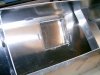
I'm looking to modify my gas tank to improve scavenging performance for the primary/lift pump. I already have a really nice Radium all in one regulator/surge tank setup that works well and I'm also happy with the lift pump itself. I like the external serviceability I currently have and the extra insurance of the surge tank, not looking to move any of the pump hardware into the tank, I simply want to improve the scavenging.

My idea is the following:

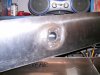
1. Install a 6"x10" oval access panel on the driver side to perform the modifications and future maintenance.
2. Add a third baffle plate 6"s off the tank end. Plate is flush fitted at the bottom with open gap 4" or so from the top. It contains a trap door at the bottom
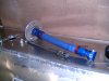
3. Install a 8"x3" Holley Hydramat feeding a bulkhead fitting. Return line is pointed back at the hydramat.
4. Install rollover valve/vent at the top driver side.

Here's a sketch of what I'm trying to describe:

IMG_20200516_234243.jpg


I'd like to get your thoughts on this and wondering if this design can be improved. Also I'd like to know what type of aluminum is needed for good weld-ability.

Thank you
 

Neil

Supporter
Mark;

6061-T6 is a good all-around aluminum alloy. Strong, weldable, and reasonably formable. 5052-H32 is also weldable, more formable, moderate strength, and good corrosion resistance. Either would work. 5052-H32 can be bent to a tighter radius and due to its better corrosion properties it would my choice.
 
Thanks Neil, I'll read up on 5052-H32.

You can weld different aluminum alloys together right, is that a correct assumption?
 

Howard Jones

Supporter
If I did mine again I would use Hyrdamat also. I think you don't need the longitudinal bulkhead with the trap door in it. Simply place the Hydramat in the center section. Maybe make the hydramat a bit bigger, 12" X 12" and run the hose to it from the end. The Hydramat works so well that I believe it will pick up all the fuel right down to the last drop.

Roadrace cars usually pick up fuel from the center rear of the tank. If you want to be sure it pick it all up you can put a small sump in the center rear of the bottom of the tank like I did. Then put a smaller Hydramat in it. That's how I would do it over again.
 

Attachments

  • HPIM0906.jpg
    HPIM0906.jpg
    159.4 KB · Views: 437

Neil

Supporter
Thanks Neil, I'll read up on 5052-H32.

You can weld different aluminum alloys together right, is that a correct assumption?
Both alloys need to be weldable, of course. Consult a welding source for a recommendation of the best alloy welding rod for that combination of alloys.
 
Thanks for the input Howard. The tank is a little over 10" wide so that does cut down on the hydramat possibilities quite a bit.
 
Why not drop a sump section with hydromat down between the 2x2 supports?

I also have the radium surge tank. But I'd like to increase the tank size so am thinking about building a tank that uses all the side-to-side space and has the pressure pumps in the tank. Using hydromat in a sump and some baffles is my plan.

5052 would be my go-to for a new tank.
 
I think that's a really good plan Frank for the configuration you're describing. How do you plan to route the fuel line into engine compartment?

For a more conventional SLC tank setup where the tank span leaves room on the side or the pumps are external I see a few issues with the sump in the middle idea:

1. You have a 4' minimum hose run to the lift pump and maybe a few more feet if the pump is in the engine compartment. That distance includes one foot of vertical lift from pickup to top of tank. Mounting the pump on top of the tank could mitigate that a bit but few lift pumps will fit in that space. With the driver side pick up idea the lift pump is mere inches away and there's no vertical lift involved. This item alone is a deal breaker for me for trying to centrally locate the pickup.

2. A 1.5" deep sump in the middle isn't going to be as effective as a tall enclosed box with a trap door which is pretty much impervious to g force. The fuel has nowhere to go, it's trapped. I'm rationalizing purely theoretically here, they're probably both sufficient in the real world but on paper I see a shallow sump in the middle having lower containment ability.

3. The shifter cable pass-through tube looks like a bit of fun to work around. In Howard's photo(older tank) the angle of that tube looks pretty mild but on my tank it's really diagonal. I can't clearly tell but it looks like it's pretty much cutting through the area that needs to be modified for a central pickup setup.
 
I think that's a really good plan Frank for the configuration you're describing. How do you plan to route the fuel line into engine compartment?

Ignore my proportions, this is based of guestimates of size. But you get the idea. I have a 'firewall' behind the tank. I'd use bulkhead fittings (as I do now) where the cutout is for pressure and return. I will modify the fuel tank 'cover' to clear the expanded plate on top that allows access to the fuel pumps - and probably make that section removable w/o having to remove the complete cover.

The through tube is not on the floor of the tank, so it's only a small hindrance.

With pump(s) outside of the tank, you could have a central pickup using an aluminum tube, and still have it exit on the side/bottom where the current one does. That would eliminate the "lift", but would not shorten the run significantly. Alternatively, you could use a flexible/weighted pickup, but that's probably not the best idea for a 'maintenance free' design.

Lots of valid ways to skin this cat. My goals are more fuel and reduced complexity. I think this fits those in my case.
 

Attachments

  • FuelTank_2020-May-28_08-31-23PM-000_CustomizedView81089566810.png
    FuelTank_2020-May-28_08-31-23PM-000_CustomizedView81089566810.png
    61.1 KB · Views: 334
  • FuelTank_2020-May-28_08-31-36PM-000_CustomizedView20991994018.png
    FuelTank_2020-May-28_08-31-36PM-000_CustomizedView20991994018.png
    15.8 KB · Views: 332

Howard Jones

Supporter
Mark, I should add that my car is carbureted. I have a single pump mounted on the outboard chassis rails alongside the engine. Pump is set to 6 PSI. It picks up every bit of fuel in the tank on a road race course down to the last 1/4 gal or less. I also pump from the top center of the tank, out a roll over valve, across the tank to the side, out through the firewall and to the filter and the pump. Then up hill to the carb. No problem whatsoever.

I purposely covered all the bungs on the bottom sides of the tank so to prevent any fuel leaving the tank except out the top. Never leaks fuel and never will. I can also remove all the pieces, level sender, pickup, and fill plate from the tank, without draining it. Something to think about...…...

Here's a picture of home made pickup and it's mounting location. The pick up end is sitting on the bottom of the sump.

I run the car only at track days that are typically 30 min sessions. I used about 6 gals per session at high speed tracks like COTA. The tank holds about 15 gals and I start the first session with about 10 gals in the tank, adding 6 gals after each session, Never have run out of fuel, That is really BAD form!

With a full tank the car will run an hour and have a safety margin, just. I can't drive the car hard that long anyway.
 

Attachments

  • HPIM0904.jpg
    HPIM0904.jpg
    162.7 KB · Views: 343
  • HPIM0915.jpg
    HPIM0915.jpg
    146.2 KB · Views: 335
  • HPIM0917.jpg
    HPIM0917.jpg
    213.9 KB · Views: 349
  • HPIM0918.jpg
    HPIM0918.jpg
    192 KB · Views: 367
Last edited:
I see what you're saying Howard. From a tank connection safety perspective that is really safe, you've only got a pickup and a vent connector both on top and both have rollover valves installed so if you go upside down the only fuel that can burn is what's left in the lines. The only improvement left there is a rollover valve for the fill tube for the event that the spider is compromised in the fuel fill area.

The way I've approached it for my car is to keep all the pumps, filters and surge tank next to the gas tank with only one line exiting to the engine which I keep as far inboard as possible. In the event of a crash the ECU will kill the pumps which will act as the flow stop. The structure around the gas tank and driver is the most well protected of the car so I figure if there is an impact strong enough to sever those fueling components then I'm about to meet some hot chicks in hell shortly anyway.
 

Neil

Supporter
Mark;

Adding an impact switch in series with your electric fuel pump is an additional safety measure. This way you don't rely solely on the ECU to cut off the pump in the case of a crash.
 
I've been making some progress with the tank modifications. It's mostly done but before installing the HydraMat I thought it would be a good time to run some before/after tests with the new chamber+trap door to get a feel for the kind of improvement that can be expected in the real world. I recorded my results as I think it could be useful data for other builders as well.

I setup the test with a 13" lift of the right side which created a roughly 20 degrees tank tilt, essentially simulating what would happen during a left turn. My physics knowledge isn't super but I figure that is equivalent to 0.5 G cornering. Something that should be easily achieved during street driving. If there's a physics wiz out there I'd appreciate a verification.

The improvement is pretty significant over stock as evident, the chamber is quite effective even down to 2 gallons. The trap door that I used is an ATL unit which isn't fully sealed so the chamber is always in a state of slow leak down when corning forces are pulling. There are other units out there that use an O-ring for a superior seal but I think it would be over kill.

The last test in the video is simulating a right followed by left turn, basically what you'd encounter during an S turn. This is where I believe a tall contained chamber has a clear advantage over a sump, specially at higher g force values. The right turn forces most of the fuel into the chamber where it gets locked, the leak down rate is still constant but the reserve is so much greater for a longer fuel supply. In a way it's acting as an accumulator. That test was done with just 1 gallon in the tank and yet the chamber level is quite high, with 4 gallons the chamber will overflow back into the rest of the tank.


Howard Jones

Supporter
I rest my case. Put the pick up in the center. The center sump system seams to work pretty well in a road race application. If a larger sump than mine was used in the center section (I would recommend the entire available area between the chassis tubes) and a hydra mat was also used in the sump I think you have the problem solved with out any active pieces such as trap doors.

I like the trap doors it's just that I like failsafe non dynamic systems instead of (hinged doors) where possible better.

Cool test and good data...…..Thanks for that.
 
Last edited:
I've been held up for a couple of weeks waiting to get a hold of a non expired ClickBond tank adhesive system to fasten the HydraMat down onto the bottom of the tank. Summit sent me 2 bad ones and a Holley drop ship ended up in back order. I finally called around and found one at FlightShop.com, those guys move a lot of volume so they had plenty on hand.

Tank is all buttoned up and back in the car and I have a video to share of the HydraMat in action. The promo videos don't lie this thing lives up to it's hype. I pretty much started the lift pump dry and added a couple of ounces of gas and it just runs smoothly with literally a few millimeters of gas skimming the bottom of the tank.

 
Here are a couple of shots of the build. The car is finally back on the road again. Before filling up the tank I took the opportunity to do a low fuel level test drive with 1.5 gallons in the tank. I did the hardest left turns I could do in a local parking lot, not quite high g driving but that's what was available. The results are good, the lift pump never hit air.

IMG_20200608_004421.jpgIMG_20200608_004443.jpgIMG_20200610_210432.jpgIMG_20200612_142937.jpgIMG_20200711_014315.jpgIMG_20200712_165450.jpgIMG_20200712_165903.jpgIMG_20200712_183630.jpgIMG_20200717_193849.jpgIMG_20200717_194015.jpg
 
Back
Top