Original Engine Mounting Bush

Hi Team.

Just checking in, has anyone got any details/dimensions or sources for the rubber engine mounting bush used on the original cars?
part, "3/3505 - Bush, Engine MTG", 2 number required out of the parts book.

The outside diameter would be 1.497 to 1.498" based on GT40P-1-2562 as published in GT40 Uncovered.
Depth or length of the larger housing would be 1.75" in length.
The diameter of the hole in the upper engine mounting bracket is 17/32" (GT40P-1-2084)
So I presume it was either a 1/2" bolt or a 7/16" bolt used for securing it. 1/2" would make more sense.

If a similar mount was used to that on the rear support member (see drawing bellow), would that make the inner sleeve 2" long, with a 1/8" lip at each end?

I cant recall ever seeing a picture of this bush or seeing it discussed?

silentbloc-vibration-damper-e21026-jpg.109659


Picture of the support member bush borrowed from @Doc Watson thread, and supplied by @JIMMYMAC

https://www.gt40s.com/threads/class...is-5-doc-watsons-car.34359/page-8#post-554076

Thanks
 
James, whats the story behind that photo? I recognize the counter top from your other posts, why have you got so many?
enough for 11 cars?
 
Thanks James.

I was trying to work out if I needed extra bushes for somewhere else on the car!

the sloping bit of the upper bolt on bracket, that bit goes towards the front of the vehicle doesn't it?

I got a bit more done on them tonight, about to head to bed though. Get some more done tomorrow.
 

JimmyMac

Lifetime Supporter
Ryan,
Yes and remember that the top of one bracket is shorter to avoid a clash with the oil filter boss.
 
Last edited:

Morten

Mortified GT
Supporter
And the left & right engine mounts differ in size too, with the offset chassis mounts. All good fun to understand the many reasons why its built like it was.
 
Yes, both upper engine mounting brackets are angled though.
I knew about the oil filter, as the mounts on the block are offset by ~1.25" for this reason. I just assumed that the mounting brackets were angled for clearance to other ancillaries on the front of the engine.
I'm still trying to work out the position of it all. seems like drawing 2077 was superseded by drawing 2754 which I have not seen just yet. 2077 shows some depressions in the mounting face, which I have not noticed on the cars. You never see photos of this area though. Its all within about 1/4" though and you have to zoom in to see which side of the line stuff is sitting on.

Just going to check the clearance of the oil pan before i go to far as well.
 

JimmyMac

Lifetime Supporter
Yes, both upper engine mounting brackets are angled though.
I knew about the oil filter, as the mounts on the block are offset by ~1.25" for this reason. I just assumed that the mounting brackets were angled for clearance to other ancillaries on the front of the engine.
I'm still trying to work out the position of it all. seems like drawing 2077 was superseded by drawing 2754 which I have not seen just yet. 2077 shows some depressions in the mounting face, which I have not noticed on the cars. You never see photos of this area though. Its all within about 1/4" though and you have to zoom in to see which side of the line stuff is sitting on.

Just going to check the clearance of the oil pan before i go to far as well.

This depression ?

Engine Support Haunches.jpg
 
@JIMMYMAC - not that depression, I will try and cover it below, responses are coming in as I am writing this......

I have been pushing on. For those interested, this is the amount of drift, unknown or possibly just construction tolerance within the plans. It looks like I need to raise the engine up 0.27" in order to get part "GT40P-1-12084 'Bracket - Engine Mounting - Upper R.H.' " to sit inline or in plane with part "GT40P-1-2077 'Support - Engine Mounting Brackets - R.H.' ". This would put the engine mount bosses on the side of the block, very very close to 3" above the horizontal 0" datum line, which sounds very convenient, and possibly like a very believable number. It would line up with a 1-2-3 machinist block just nicely and allow something like this to have been used when setting up the engine on a build table. Note to self, I will have to check the offset from engine mounting bosses to the sump face as i don't know if this is 3" or not. Another thing to confirm.

52744666770_6293ab365a_h.jpg


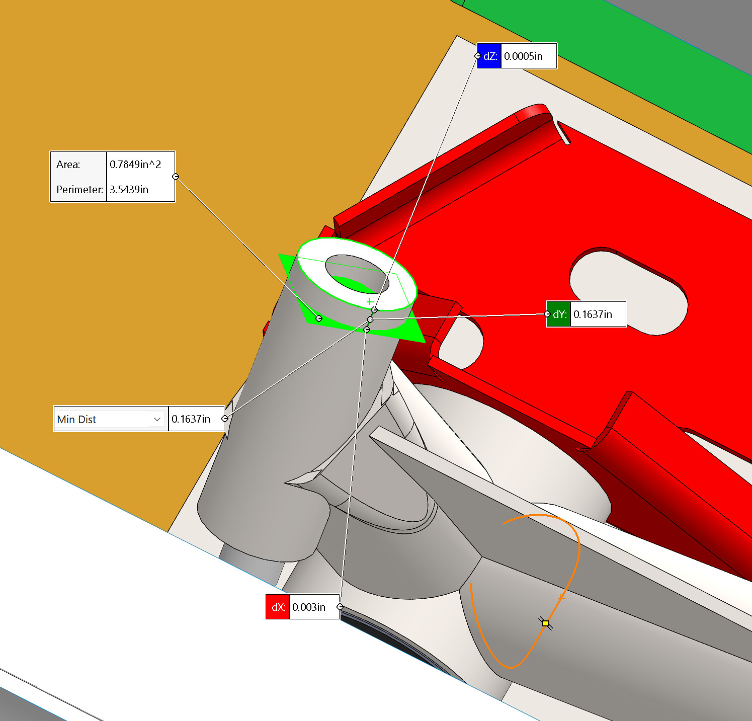
Ok, this below image will be a bit hard to see or understand without some extra explanation. So i will try and explain what each part is.

The Grey welded engine mount is where i had originally placed it to align the crank shaft axis with the transaxle input shaft axis, based on the ears on top of the gear box. This is based on having the engine mounted horizontal and parallel to the horizontal axis of the drawings. The engine mount is as per drawing GT40P-1-2562.
The purple engine mount is engine mount 2562 only that its raised up by 0.18". This is what I am trying to work out.

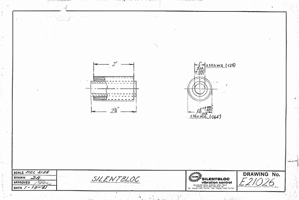
the mentalistic bush is 13-1657 as discussed above in this thread and is mounted concentrically to the grey engine mount. The central tube is 2" long.

The red upper bracket is GT40P-1-2084 and is located such that its 17/32" mounting hole is concentric and coincident with the top of the metalastic bush. This is where the 1/2" bolt would go through to secure the engine mount to the chassis.

Now the solid grey rectangle that I have sketched around with the bold black line is the cross section of GT40P-1-2077. part titled "Support Engine Mounting Brackets - R.H." and is the main chassis components that @JIMMYMAC is showing above in post #10 of this thread.

This is drawn in position based on the location in its drawing.
@David Deschamps It is 16 SWG material (0.064" thick) projected upwards from the plane nominated in the drawing as that is how I read the dimension call outs.

Drawing 2077 is in the GT40 Uncovered book, so you would need to refer to that due to copyright.
On the drawing/projection of 2077 in the book, matching the projection below it shows that there is a depression in this plate, cross section DD. The depth of this depression would be 0.08" but it is only in the area around the metalastic bush, and not the upper bracket. So i either need to move the cross section of the plate down, or the engine up.

The last revision of drawing 2077 was Rev C on 12 Feb 65
On drawing 2107 which is the assembly of the whole engine mount area or sub assembly (revision C, dated 08 June 65). It lists parts 2076 and 2077 being deleted and parts 2754 and 2757 added to replace them. So shortly after drawing 2077 was updated for the last time, it was completely superseded by 2754
(2076 is the closing plate on the bottom of the lower engine mount of the chassis and 2057 supersedes it)


52744741488_cbb42bd644_h.jpg


At this point, I am not sure which option to chose.
Do I
  1. Raise the engine at the front, so that it no longer sits level in the chassis and with its crank parallel to the horizontal plane of the drawings. Note that the engine mounts have the bolts that connect to the block canted backwards at a 40' angle and they are not parallel with the main chassis bolt when viewed from the side of the vehicle. Note I am not referring to the 45° on the front/rear view From the sketch below it looks like i need to raise it up that 0.27" at the chassis mount.
  2. Lower the cross section of part 2077 so that it lines up with where the engine wants to sit based on the position of the rear transaxle mounts. I don't have drawing 2754 to confirm what was done for the part when they superseded 2077.
It sure would be interesting to see some photos of early cars, pre 08/06/65, that show the original engine mount configuration. I wonder did the engine get raised? Does this date coincide with the dropping of the Colotti transaxle and the adoption of the 5DS-25? Or did the engine get raised by 1/4" for some reason
More research needed. Just goes to show why these things take so long to draw up. You have to research and reverse engineer the changes.
I might start sketching in a few of the other drawings i have, or scaling those and dropping them in as well. See if that changes my thinking.

I suppose its good to see that through out all this, the parts are within 1/4" in CAD when there is no tolerance. A lot of these parts were hand formed on the original cars and then drawn up afterwards.

Hopefully what I have written can be understood and is of interest to some.

Ryan
 
Thanks T.

The assembly on the left, is drawing GT40P-1-2107.
The drawing on the right is GT40P-1-2077. This shows the depression and cross section D-D that i was talking about above.
 
I am busy going through "GT40 Uncovered". Page 113 covers the ZF 5DS25. It notes that 2 ZF equipped cars were tested at Monza on 30-September 1965, The purpose of the test was to evaluate the suitability of the Transaxle for use in 24hr endurance events.
This date correlates well with the revision histories above and the modifications to the chassis that would have been necessary to accommodate the transaxle.

Page 51
drawing 2591 which shows the mounts for the ZF is dated 10/08/65
drawing 2187 - support member assembly for the ZF dated rev B 13/07/65 (rev A first issue 26/11/64)

looks like works were well underway to install the ZF by November, following the failures on the 20th June at Lemans.

gt40p-1-2591-jpg.44486
 
Note to self, I will have to check the offset from engine mounting bosses to the sump face as i don't know if this is 3" or not. Another thing to confirm.

Ryan

From the 3d scan data. This is the Port side rear engine boss to the sump rail on a 302 block. "dZ" of 1.6" is the measurement I was after.
Ford drawings list a measurement of 1.48, however this is to the crank center line not the sump rail.
52744068427_406e9e4b30_h.jpg


I also checked the distance from the same boss to the top of the cap bolt. The height measurement "dZ" of 4" is the one we are interested in.

52745002035_668e7bd7e7_h.jpg


As there is a bunch of structure in the chassis that sits below the Zero line, the table surface would not be at the Zero line. So my original ramblings about the 1-2-3 block can be ignored.

The Aviaid sump was 6.5" deep, so 6.5 + 1.6 = 8.1..... not a helpful measurement, other than knowing it puts the sump 0.1" below the bottom of the chassis. Wonder why/how they set the block up when they were developing it all.

Ryan
 
Last edited:
Slept on it, thought about it some more.
Figured that the engine mount plans have a 40' angle to them, which is 0.67° for a reason. Probably something as simple/important as to allow air to make its way towards the front of the engine and the bleed ports at the front of the heads.

So I have been fiddling around in CAD trying to work out how to get the whole drive line tilted up by that amount, based on the pivot point being the rear removable support across the top of the transaxle.

With that now done, and the drive line sitting at that angle I have aligned the engine mounts with the bosses on the block, and then placed the rest of the bushes and top plate concentric with the engine mount. I need to do another check on my work but I am a lot happier with how that is sitting.

The plate that i had roughed in for the top face of 2077 is unchanged from the last pictures on the 13th. So that gives you an idea of how far the front of the engine moves up.


52745900142_037d8f0da4_h.jpg


Ryan
 
Back
Top