Rob's AK40

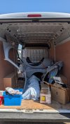
As you all know, there isn't much room inside a GT40. So I can fit (I'm 6'3"), there are three things I'm going to make small more room:-
  1. Low the floor.
  2. Re-position the pedals to move them 3" further forward.
  3. it a Gurney bubble to the driver's door.
I've done the pedals. Next is the floor. Therefore, I have fitted a tray to either side of the car to lower the section with the seat by 30mm.

It is just mocked up at the moment. It'll need to be Nyalic'd and sealed and I will also weld some steel brackets underneath to provide better stiffness for the seat mountings.

1766411711114.png
 
The gear stick is located on the sill. I quite like the exposed mechanism but I'll need to cover it all before the IVA.

The transaxle has a dog-leg 1st gear with Reverse gear straight in-front. Therefore there is a lock-out mechansim to prevent expensive mistakes. I think I'll need to make some minor tweaks as the current one is very easy to move and could easily allow accidental engagement of reverse gear.

1766412383739.png
 
Last edited:
Hi Rob, looking good, I'm doing the same with the paneling (although I'm using 120/240/400 wet and dry + scotchbrite), looking at your panels at the front they seem to have more holes than mine, are these ones that you've added? or I'm wondering if they are just different from AK ...

Also with the lowered floor, AK don't seem to weld in extra steel brackets so I'm wondering are they really necessary? obviously it's far easy to weld them in now rather than later
 
Hi Rob, looking good, I'm doing the same with the paneling (although I'm using 120/240/400 wet and dry + scotchbrite), looking at your panels at the front they seem to have more holes than mine, are these ones that you've added? or I'm wondering if they are just different from AK ...

Hi Chris. Great to hear from you.

I have already mocked up the front of the car with all the wiring, brake pipes, cooling system, etc. and added extra holes to route these through the panels. I decided to do this before riveting the panels on as I was concerned about access with a drill and also the risk of scuffing the sheet metal with the chuck.

Of course, the consequence of this approach is it takes much longer to finish!
 
Last edited:
Also with the lowered floor, AK don't seem to weld in extra steel brackets so I'm wondering are they really necessary? obviously it's far easy to weld them in now rather than later

I talked to Jon at AK about this. He doesn't believe it is necessary and has not see any problems without additional bracing.

For me, I fitted similar lowered aluminium floor trays to my Westfield. These started splitting along the folds on the floor. Since I welded steel brackets to attach the seats, it has been fine.

To be fair, it took over 10 years for the aluminium to fail on the Westfield and the car had completed dozens of track events on slick tyres with high cornering G-forces and an 85kg driver!

The AK40 is more than likely to be OK without additional bracing. However, it is easier to do now before fitting the floor. :)
 
Last edited:
It is time to start fitting out the engine compartment for all the wiring and fuel lines, etc. In order to do this, it is time to take the engine and 'box out again!

As you can see in the photo below, there is just fresh air inside the bellhousing. I have been looking for a flywheel and clutch. I know many builders use the Mustang flywheel. However, this will not fit inside my bellhousing. I have heard you can use a 3.0 V6 Essex Capri unit which bolts straight on to the 302 V8 crankshaft. Any help or advice here gratefully accepted. :)

1771080996910.png
 
I've had to move the engine mounts forward by 40mm to ensure the bellhousing fits within the engine bay and, more importantly, the driveshaft position on the transmission lines up with the rear hubs. I have welded in sleeves in the new mounting positions to ensure the chassis box section is not crushed when tightening the engine mounts.

1771081090023.png
 
I have installed the main pipes which feed coolant between the engine at the rear and the radiator at the front of the car.

As the pipes are inside a tunnel that runs down the centre of the car through the cockpit, the heat from the coolant will be welcome during the winter but less so during the summer months. Therefore I have wrapped the pipes in Nitrile foam which provides a thermal barrier and is water and flame retardant.

1771081243273.png
 
I have fitted the engine bay and bulkhead panels to the chassis. These have all been treated to a Nyalic coating to protect the aluminium.

I have not fitted the horizontal panels on either side yet. These are where the fuel system (pumps, filters, regulator, swirl pot, etc.) will be located. I will mock-up everything on a plywood sheet for now. This will allow me to re-position everything until I'm happy with their location without the aluminium panel ending up like Swiss cheese!

Now it is time to put the engine back in once again to begin finishing all the cooling system and routing all the wiring.

1771081478430.png
 
Hi Rob, I have to say your panels looks perfect :) I'm just wondering how you managed to get 29 and 48 in without trimming them?
 
Hi Rob, I have to say your panels looks perfect :) I'm just wondering how you managed to get 29 and 48 in without trimming them?

Thanks Chris.

Yes, those two are a little tricky!

I managed to get 48 in without too much of a problem; a slight twist just to clear the bracket that the trailing arm is connected.

29 put up some more resistance! I firstly needed to ensure the flange on the engine side of the panel was clear of the horizontal box section (that the engine mount is bolted to). I located the slot in the top into the corner where the round tube meets the bulkhead. The panel required a slight bend into position but this isn't permanent and the panel soon springs back straight again once in position.
 
I have put the battery in place. I have to work out how to modify the battery terminal covers otherwise make some new ones.

On the right is the Drier for the Aircon. I'll add more details on the aircon system in a later post.

The 'Elephant in the Room' is on the left of the photo; the Electric Water Pump. I don't know what I was thinking when I installed it. In it's current orientation I doubt it'll work properly. When I fill the cooling system it'll be half full of air and the impeller will spin without doing much pumping. I have two options: -
  1. Relocate it to the engine bay and make sure it is oriented correctly.
  2. Leave it where it is and add a bleed screw at it's highest point.
Option 1 is almost certainly the way to go. However, I would be interested in exploring Option 2. Has anyone heard of drilling and tapping a fitting in an EWP? Or am I just living in denial! :)

1771501172612.png
 
Hi Rob,
I would have thought that your electric water pump is too low. My air bleed point is above the top of the engine which is where the air will naturally go. I'm sure Jerry Irwin will see your post and give constructive input.
Cheers
Steve.
 
I have put the battery in place. I have to work out how to modify the battery terminal covers otherwise make some new ones.

On the right is the Drier for the Aircon. I'll add more details on the aircon system in a later post.

The 'Elephant in the Room' is on the left of the photo; the Electric Water Pump. I don't know what I was thinking when I installed it. In it's current orientation I doubt it'll work properly. When I fill the cooling system it'll be half full of air and the impeller will spin without doing much pumping. I have two options: -
  1. Relocate it to the engine bay and make sure it is oriented correctly.
  2. Leave it where it is and add a bleed screw at it's highest point.
Option 1 is almost certainly the way to go. However, I would be interested in exploring Option 2. Has anyone heard of drilling and tapping a fitting in an EWP? Or am I just living in denial! :)

View attachment 151923
hi rob,
i went same route, but my location was even worse with u bends every where... ( air pocket would not shift ) and considered a bleed,,, but went the route of relocation to engine end.
Jerry
 
Like buses, you wait ages for them to turn up and then they all arrive together! Not only was my bodywork ready, but I also took delivery of my Jenvey throttle bodies.

My rusty old cylinder heads make the throttle bodies look even better!!
 

Attachments

  • PXL_20260514_083059304.MP (1).jpg
    PXL_20260514_083059304.MP (1).jpg
    391.6 KB · Views: 28
Back
Top