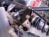
Be careful not to sit the car on its tires fully loaded with an engine and gearbox installed without the top cross brace in place. The geometry of the rear chassis without the cross brace will tend to transfer the loads in such a way that the top chassis rails where the shocks are mounted will be forced together transversely.
This can cause quite a lot of excessive moment-arm load on the bottom chassis welds, especially at the point where the vertical solid rear chassis rails are welded to the horizontal bottom chassis rails all the way to the rear. This will also tend to force the top rear cross brace mount points together somewhat.
That may be the cause of your seemingly too wide cross brace.
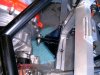
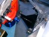
Support the rear of the car, without the tires and wheels on, it at the bottom near the junction of the forward solid down chassis element and the rear motor/ gearbox mounts with a jack stand at each side under the horizontal cassis tube's forward end. Now install the cross brace. All four rod ends should be wound nearly all the way in with rod end jam nuts installed, You may need to turn each rod end out a couple of turns but that would be it. Place washers, if needed, to shim up any space between the rod end thru-hole and the u-shaped top aluminum chassis element so as not the force pinch the vertical aluminum forks/tabs.
I bet it fits now.