

You are using an out of date browser. It may not display this or other websites correctly.
You should upgrade or use an alternative browser.
You should upgrade or use an alternative browser.
Chuck and Ryan's RCR Build
- Thread starter CESLAW
- Start date
Dasboard is looking good Chuck!
Wiring, Part I, Fuse box location
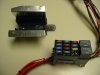
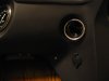
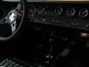
After much thought we decided to locate the fuse box on the lower right, passenger side, of the dashboard. The Painless 14 circuit micro fuse harness, #10130, is being used rather than the harness supplied with the car. The mini fuse box is only 3 ½ x 2 inches so it tucks up rather neatly with the fuses accessible from the bottom of the dash. This will further simplify the wiring as well. A rectangular opening was cut and an aluminum bracket fabricated to support the fuse box.
Openings 2 ½” were cut out of the chassis behind the dash for the left and right dash vents. A large section was cut out to clear the speedometer and the fuse box. Since there are two channels riveted to the under side of the chassis behind the dash panel, cutting out that section should have no impact on the strength of the assembly.
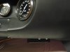
The fuse box cover is rather inconspicuous from the passenger seat, as seen in the picture below, yet the fuses can be easily accessed.
After much thought we decided to locate the fuse box on the lower right, passenger side, of the dashboard. The Painless 14 circuit micro fuse harness, #10130, is being used rather than the harness supplied with the car. The mini fuse box is only 3 ½ x 2 inches so it tucks up rather neatly with the fuses accessible from the bottom of the dash. This will further simplify the wiring as well. A rectangular opening was cut and an aluminum bracket fabricated to support the fuse box.
Openings 2 ½” were cut out of the chassis behind the dash for the left and right dash vents. A large section was cut out to clear the speedometer and the fuse box. Since there are two channels riveted to the under side of the chassis behind the dash panel, cutting out that section should have no impact on the strength of the assembly.
The fuse box cover is rather inconspicuous from the passenger seat, as seen in the picture below, yet the fuses can be easily accessed.
Attachments
Wiring, Part II
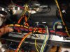
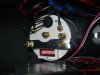
We opted to use a Painless wiring harness. Painless makes a wiring harness kit that has a mini fuse box with 14 circuits well matched to the GT-40’s needs, Micro Fuse Harness, #10130. They also make assorted accessories, like auxiliary fan and fuel pump relay kits. The quality of their products is good. When soldering connections with the Painless wiring there was never a problem with the insulation melting, a problem often seen with ‘standard’ wire if a bit too much heat is applied.
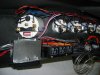
An aluminum half inch angle bracket, about twelve inches long was secured to the lower portion of the dash about three inches from the back edge. This served several functions. First, it lended some structural strength to the lower portion of the fiberglass dash. Second, it provided a backing support for the AC panel mounted below the dash. Third, eight holes were drilled along the vertical surface and three small bolts were placed to use as common ground points. Fourth, it provided a good point to tie off the completed wiring harness making it secure and free from movement.
We divided the dashboard wiring into four phases. First the switch assemblies were wired on a temporary basis. Each circuit was tested as it was wired. Second the switch assemblies were permanently wired into the car, both to the fuse box and to the wires going to the various remote locations. Third, the gauge lights were wired. Finally the gauge sending units were wired. When this was completed the rat’s nest of wires was neatly organized and wire ties were liberally used to secure everything.
We made sure there was a good six inches of slack on the switch wires so that the panels could be removed and dropped out of the way to give good access, should that be necessary.
We opted to use a Painless wiring harness. Painless makes a wiring harness kit that has a mini fuse box with 14 circuits well matched to the GT-40’s needs, Micro Fuse Harness, #10130. They also make assorted accessories, like auxiliary fan and fuel pump relay kits. The quality of their products is good. When soldering connections with the Painless wiring there was never a problem with the insulation melting, a problem often seen with ‘standard’ wire if a bit too much heat is applied.
An aluminum half inch angle bracket, about twelve inches long was secured to the lower portion of the dash about three inches from the back edge. This served several functions. First, it lended some structural strength to the lower portion of the fiberglass dash. Second, it provided a backing support for the AC panel mounted below the dash. Third, eight holes were drilled along the vertical surface and three small bolts were placed to use as common ground points. Fourth, it provided a good point to tie off the completed wiring harness making it secure and free from movement.
We divided the dashboard wiring into four phases. First the switch assemblies were wired on a temporary basis. Each circuit was tested as it was wired. Second the switch assemblies were permanently wired into the car, both to the fuse box and to the wires going to the various remote locations. Third, the gauge lights were wired. Finally the gauge sending units were wired. When this was completed the rat’s nest of wires was neatly organized and wire ties were liberally used to secure everything.
We made sure there was a good six inches of slack on the switch wires so that the panels could be removed and dropped out of the way to give good access, should that be necessary.
Attachments
Wiring Part III
Details of the switch circuits follows.
Windshield wipers
The GT 40 kit came with an after market (not Lucas) brand wiper motor with a four wire plug. Two wires activate the low and high speed circuits. The other two activate the park function. Using a battery charger as a power source (which is circuit breaker protected and thus preferable to a battery for this purpose) temporary connections were made to determine how the circuits should be wired. Connections were then made to the Lucas wiper switch, 35927. A GM Style plug was then added for ease of servicing or modifications. We are adding a Lucas windshield washer which looks vintage, so its power source was tapped off of the wiper power source as well. (Hard to believe, but one can see Lucas type windshield washers on some vintage photos, hence why not on a reproduction?).
Fuel pumps
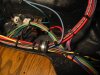
Painless was the source for the two fuel pump relays, #30101. These are the weather proof version, for a bit of added security. We used a red relay wire on the left (port) switch and a green on the right (starboard) switch. All circuits were checked as they were completed while the components were sitting on the dinning room table.
Brake light
Here is a strange little extra we added. On one original GT-40, (I can’t recall which one at the moment), the mechanic placed a push button switch on the dashboard which activated the rear brake lights. When approaching a curve, the driver could push that button just before he applied the brakes to prompt the car following to hit his brakes prematurely. Ryan thought it could have real world applications, like signaling a tailgating car to back off. Wiring it involved nothing more than adding a pair of parallel wires with the brake switch at the brake pedal.
Lights
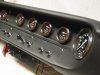
Originally we planned to place relays in the high beam, low beam and driving light circuits. But we decided to keep it simple. The Lucas headlight switch, S-31788 and the Lucas high – low beam switch, 34889, and the fused circuit supplied by Painless should be adequate to handle the power. However since the driving lights may be a halogen type light (we have not decided yet) we will likely add a relay under the front clip. All three switches are on the small switch panel to the left of the steering column. The blue high-low indicator is directly above the switch, so which switch to flip for high beams is obvious.
Auxiliary fans
The auxiliary fans will be activated with a temperature switch that goes on at 185 degrees and off 170 degrees, with an appropriate relay and fuse. Painless supplies the parts in their kit, 30129. However, the option of being able to manually override the thermostat switch was facilitated by a dash mounted switch. The switch simply grounds the connection to the thermostat, in parallel to the activation circuit. In addition the AC trinary pressure switch will also be wired into the circuit, so there will be three separate means of activation, which could work concurrently or independently depending upon the cooling needs of the engine.
AC and Heater
A small auxiliary panel was made to accommodate the controls for the heater and AC system, as noted in a previous post. One switch operates the fan, a second the AC temperature, and the third is a pull switch to control the water flow for the heater temperature. The fire system lever occupies the first position.
The AC / Heater blower uses a lot of power. It has four positions: off, low, medium and high. Using the charger amp gauge as a crude indicator, the high position draws around ten or more amps of power. That seems like a lot of power to draw through a small dash switch, so we decided to use the extra relay included with the Painless fuse box for the high speed blower circuit. We shortened the three wire harness going from the switch to the AC / heater unit, rewiring the orange – high speed blower wire into the relay circuit.
Details of the switch circuits follows.
Windshield wipers
The GT 40 kit came with an after market (not Lucas) brand wiper motor with a four wire plug. Two wires activate the low and high speed circuits. The other two activate the park function. Using a battery charger as a power source (which is circuit breaker protected and thus preferable to a battery for this purpose) temporary connections were made to determine how the circuits should be wired. Connections were then made to the Lucas wiper switch, 35927. A GM Style plug was then added for ease of servicing or modifications. We are adding a Lucas windshield washer which looks vintage, so its power source was tapped off of the wiper power source as well. (Hard to believe, but one can see Lucas type windshield washers on some vintage photos, hence why not on a reproduction?).
Fuel pumps
Painless was the source for the two fuel pump relays, #30101. These are the weather proof version, for a bit of added security. We used a red relay wire on the left (port) switch and a green on the right (starboard) switch. All circuits were checked as they were completed while the components were sitting on the dinning room table.
Brake light
Here is a strange little extra we added. On one original GT-40, (I can’t recall which one at the moment), the mechanic placed a push button switch on the dashboard which activated the rear brake lights. When approaching a curve, the driver could push that button just before he applied the brakes to prompt the car following to hit his brakes prematurely. Ryan thought it could have real world applications, like signaling a tailgating car to back off. Wiring it involved nothing more than adding a pair of parallel wires with the brake switch at the brake pedal.
Lights
Originally we planned to place relays in the high beam, low beam and driving light circuits. But we decided to keep it simple. The Lucas headlight switch, S-31788 and the Lucas high – low beam switch, 34889, and the fused circuit supplied by Painless should be adequate to handle the power. However since the driving lights may be a halogen type light (we have not decided yet) we will likely add a relay under the front clip. All three switches are on the small switch panel to the left of the steering column. The blue high-low indicator is directly above the switch, so which switch to flip for high beams is obvious.
Auxiliary fans
The auxiliary fans will be activated with a temperature switch that goes on at 185 degrees and off 170 degrees, with an appropriate relay and fuse. Painless supplies the parts in their kit, 30129. However, the option of being able to manually override the thermostat switch was facilitated by a dash mounted switch. The switch simply grounds the connection to the thermostat, in parallel to the activation circuit. In addition the AC trinary pressure switch will also be wired into the circuit, so there will be three separate means of activation, which could work concurrently or independently depending upon the cooling needs of the engine.
AC and Heater
A small auxiliary panel was made to accommodate the controls for the heater and AC system, as noted in a previous post. One switch operates the fan, a second the AC temperature, and the third is a pull switch to control the water flow for the heater temperature. The fire system lever occupies the first position.
The AC / Heater blower uses a lot of power. It has four positions: off, low, medium and high. Using the charger amp gauge as a crude indicator, the high position draws around ten or more amps of power. That seems like a lot of power to draw through a small dash switch, so we decided to use the extra relay included with the Painless fuse box for the high speed blower circuit. We shortened the three wire harness going from the switch to the AC / heater unit, rewiring the orange – high speed blower wire into the relay circuit.
Attachments
A little extra
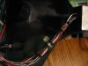
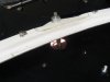
A little item that not much thought is given to, until you need it, is a power jack. Since most of our driving will be on the street, not the track, it seemed like a good idea. West Marine provides a nice water proof unit with a cover which blends in well. Marinco Model # 343576. We mounted it on the passenger side where anything plugged in would be out of the driver’s way, carefully centering it directly below the vent for aesthetic purposes. The radio “switched” power source and a separate ground were connected.
A little item that not much thought is given to, until you need it, is a power jack. Since most of our driving will be on the street, not the track, it seemed like a good idea. West Marine provides a nice water proof unit with a cover which blends in well. Marinco Model # 343576. We mounted it on the passenger side where anything plugged in would be out of the driver’s way, carefully centering it directly below the vent for aesthetic purposes. The radio “switched” power source and a separate ground were connected.
Attachments
Lovely. This will be one usable car.
Dalton
Dalton
Wiring, Part IV, Blinkers and Hazard Warning Lights
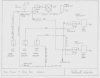
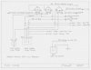
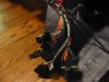
Perhaps the biggest wiring challenge was getting the blinkers and hazard warning flashers to work properly. With a GM style column mounted switch it is simple. But with a Lucas turn signal and single pole switches to activate the hazard flasher, it is a challenge.
The objectives were: (1) blinkers would work only when the ignition was “on”; (2) hazard warning lights would work when ignition was off; (3) if the blinkers were turned on, either left or right, and one then turned on the hazard warning flashers, the hazard warning flashers would override the blinkers; (4) The turn signal indicators would indicate function, with both left and right blinking when the hazard warning flashers were activated. In short, we wanted them to operate in the same manner as a conventional car.
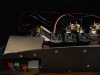
The solution was found by using three relays and a single throw double pole switch ( the same as is used for the ‘high beam / low beam’ switch, Lucas 34889). Painless relays and brackets were used. The three relays fit nicely next to the fuse box. You can imagine our delight when we flipped the switches and it actually worked exactly as planned!
Perhaps the biggest wiring challenge was getting the blinkers and hazard warning flashers to work properly. With a GM style column mounted switch it is simple. But with a Lucas turn signal and single pole switches to activate the hazard flasher, it is a challenge.
The objectives were: (1) blinkers would work only when the ignition was “on”; (2) hazard warning lights would work when ignition was off; (3) if the blinkers were turned on, either left or right, and one then turned on the hazard warning flashers, the hazard warning flashers would override the blinkers; (4) The turn signal indicators would indicate function, with both left and right blinking when the hazard warning flashers were activated. In short, we wanted them to operate in the same manner as a conventional car.
The solution was found by using three relays and a single throw double pole switch ( the same as is used for the ‘high beam / low beam’ switch, Lucas 34889). Painless relays and brackets were used. The three relays fit nicely next to the fuse box. You can imagine our delight when we flipped the switches and it actually worked exactly as planned!
Attachments
Chris Kouba
Supporter
You can imagine our delight when we flipped the switches and it actually worked exactly as planned!
That's something that belongs in one of those credit card commercials as "Priceless."
Keep up the good work. You're giving me lots of ideas for my build as well.
Starter switch
A push button switch just seems natural for a GT 40. Since Lucas switches were selected for other functions, a Lucas push button switch and two position keyed ignition switch (on – off, no accessory position) were selected. Note that the ignition switch can also be used to start the car, the push button simply parrallels the "start" position.
The keyed ignition switch needs to be securely mounted to that it will not rotate when engaged. The flat surface on one side of the threads is intended to accomplish that function, but mounting it in a fiberglass panel seemed destined to it loosening up with time. Accordingly a flat aluminum panel was fabricated from eighth inch stock. We carefully cut a hole undersized and then used a file to enlarge it and make a flat side that would not permit the switch to rotate when the key was engaged. This is a simple solution, which will hopefully keep the switch tightly in place.
The pushbutton switch will be wired directly to the powers source so one can activate the starter even when the ignition is in the “off” position. This will enable one to turn over the motor without starting the car, perhaps to get the oil moving before firing it up. .
Attachments
Wiring, Part V, Gauges
With the switch panels in place, it was time to move on to the gauges, which were straight forward.
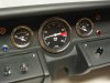
The speedometer power source is not wired with the other gauges. A ground and power wire were twisted together. The power source was connected directly to the accessory terminal of the ignition switch and the separate ground will be secured directly to the chassis ground. I am contemplating using a shielded cable or twisted wire for the magnetic pickup. This should minimize the risk of electrical interference.
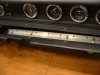
The speedometer will have to be removed to gain access to the dip switches in order to calibrate it. To facilitate removing it, knurled nuts were used to secure it to the bracket which were finger tightened rather than the nuts that came with the gauges. (Note the picture below). Plugs were used on the light wires so that the unit could be completely removed after the dash was installed. One will be able to reach behind the dash, remove the knurled nuts, and pull out the speedometer to adjust the dip switches without too much difficulty.
A couple of 12 gauge wires were screwed to the brace / buss bar. The opposite ends will be screwed to the chassis, one going to the left and the other to the right side of the chassis. When complete there will be at least three ground wires from the dash assembly to the chassis. A good ground can minimize lots of gremlins.
The kit came with a clock which we want to replace with an oil temperature gauge. Since the oil temperature gauge has not yet arrived, we installed the clock but added an extra pick up wire and the necessary connections for the oil temp gauge so that it will be an easy swap. The clock actually keeps pretty good time! The “always on” radio power source was used to energize the clock. The red reset switch was mounted just to the right of the steering column on the bottom of the dash, where it is out of sight.
With the switch panels in place, it was time to move on to the gauges, which were straight forward.
The speedometer power source is not wired with the other gauges. A ground and power wire were twisted together. The power source was connected directly to the accessory terminal of the ignition switch and the separate ground will be secured directly to the chassis ground. I am contemplating using a shielded cable or twisted wire for the magnetic pickup. This should minimize the risk of electrical interference.
The speedometer will have to be removed to gain access to the dip switches in order to calibrate it. To facilitate removing it, knurled nuts were used to secure it to the bracket which were finger tightened rather than the nuts that came with the gauges. (Note the picture below). Plugs were used on the light wires so that the unit could be completely removed after the dash was installed. One will be able to reach behind the dash, remove the knurled nuts, and pull out the speedometer to adjust the dip switches without too much difficulty.
A couple of 12 gauge wires were screwed to the brace / buss bar. The opposite ends will be screwed to the chassis, one going to the left and the other to the right side of the chassis. When complete there will be at least three ground wires from the dash assembly to the chassis. A good ground can minimize lots of gremlins.
The kit came with a clock which we want to replace with an oil temperature gauge. Since the oil temperature gauge has not yet arrived, we installed the clock but added an extra pick up wire and the necessary connections for the oil temp gauge so that it will be an easy swap. The clock actually keeps pretty good time! The “always on” radio power source was used to energize the clock. The red reset switch was mounted just to the right of the steering column on the bottom of the dash, where it is out of sight.
Attachments
Wiring Part VI, Finishing Touches
With the wiring done, wire ties were used to tightly secure everything. The main group of wires was also tied to the buss / brace referenced earlier. On the left and right sides of the dash a padded clamp was used to securely hold the harness.
Although perhaps overkill, we opted to put plugs on the wires. The wires were grouped into front and back and then separated into logical groups with a variety of two, four and six wire plugs, switching the male and female portions so that it would be even more obvious which ends go together.
We checked all the circuits, except the tach and speedometer input, with the dash setting on the dining room table. A battery charger was used as a power source. Simply grounding the oil pressure and water temp sending wires will show a full scale movement. Tooting the horn got the family’s attention real quick. The fuel sending units were temporarily hooked up, revealing that the sending units are mounted up side down and will need to be flipped over before they are installed in the tank. We marked with a pencil the relative location of “half full” so we can accurately calibrate the sending units when installed. Lights, blinkers, hazard flashers all worked as intended. The dash lights put out a nice glow, which provides a bit of illumination on the switches as well. Nice set up!
Dash completed, we decided to test fit it in the car. As the picture below shows, the control panel under the dash is fairly inconspicuous, other than that bright red “FIRE” knob. A bit more trimming and fitting of the aluminum chassis was needed to clear the vents, but nothing troublesome. Just for fun we put in the carpet, seats, hung the doors and put on the front clip. Ryan and I took a test sit. It really feels good!
Attachments
") Well done!
Well done!Beautiful...
Windshield Wiper
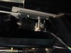
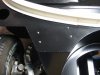
The wiper motor supplied with our RCR was a “It’s A Snap” brand. Can’t say I ever heard of that particular manufacturer before, but it is well suited to the GT. Two tips for a successful installation: (1) Lots of grease and (2) A short and direct connection between the motor assembly and the wiper cowl mount.
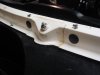
The cowl mount shaft is just long enough to make a clean, neat installation. After drilling a guide hole in the spider, we continued drilling so we had a corresponding guide hole on the chassis below. The spider was drilled with a 3/8” bit to accommodate the cowl mount shaft. We then drilled a 1 ¼” hole in the chassis to clear the shaft mechanism with plenty of room to move it around for future adjustment. The shaft was long enough so that it came to rest fully below the chassis with a quarter inch to spare.
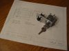
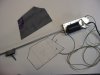
Finding a location for the motor was easy. Locating the motor forward of the evaporator on the passenger side, secured to the top surface of the chassis, provided a direct, short route for the connecting tube. The four mounting holes were elongated slightly to give some lateral movement for adjustment purposes when the spider is secured in its final position. A double thickness of sound insulation material was placed between the motor and the chassis. (We made our usual pattern before cutting the insulation material, shown in the picture below.) The mounting bracket that came with the wiper kit proved unnecessary.
The aluminum tube was carefully cut to length and the ends flared making a nice, tight fit on both ends. The excess cable was cut off, leaving a couple of inches sticking out on the opposite side of the wiper shaft mechanism. A short section of aluminum tube to protect the free end was added with the necessary flare to keep it in place..
Grease, grease and more grease. The cable was thoroughly greased. The slide guide mechanism was also thoroughly greased.
The final step was to test run the unit to make sure the sweep was appropriate. We removed and replaced the unit a couple of times before finding the right hole on the motor assembly for getting an appropriate arc.
Next we cut a piece of aluminum and expoxied it on the back side of the clip to give a bit more strength to the wiper shaft mechanism. We also drilled the hole for the windshield washer sprayers, adding a 7/8” access hole to the front of the clip for access to the bottom side of the nozzle so that the connecting hose could be added later. A black plastic plug covers these holes.
This part of the project went together well.
The wiper motor supplied with our RCR was a “It’s A Snap” brand. Can’t say I ever heard of that particular manufacturer before, but it is well suited to the GT. Two tips for a successful installation: (1) Lots of grease and (2) A short and direct connection between the motor assembly and the wiper cowl mount.
The cowl mount shaft is just long enough to make a clean, neat installation. After drilling a guide hole in the spider, we continued drilling so we had a corresponding guide hole on the chassis below. The spider was drilled with a 3/8” bit to accommodate the cowl mount shaft. We then drilled a 1 ¼” hole in the chassis to clear the shaft mechanism with plenty of room to move it around for future adjustment. The shaft was long enough so that it came to rest fully below the chassis with a quarter inch to spare.
Finding a location for the motor was easy. Locating the motor forward of the evaporator on the passenger side, secured to the top surface of the chassis, provided a direct, short route for the connecting tube. The four mounting holes were elongated slightly to give some lateral movement for adjustment purposes when the spider is secured in its final position. A double thickness of sound insulation material was placed between the motor and the chassis. (We made our usual pattern before cutting the insulation material, shown in the picture below.) The mounting bracket that came with the wiper kit proved unnecessary.
The aluminum tube was carefully cut to length and the ends flared making a nice, tight fit on both ends. The excess cable was cut off, leaving a couple of inches sticking out on the opposite side of the wiper shaft mechanism. A short section of aluminum tube to protect the free end was added with the necessary flare to keep it in place..
Grease, grease and more grease. The cable was thoroughly greased. The slide guide mechanism was also thoroughly greased.
The final step was to test run the unit to make sure the sweep was appropriate. We removed and replaced the unit a couple of times before finding the right hole on the motor assembly for getting an appropriate arc.
Next we cut a piece of aluminum and expoxied it on the back side of the clip to give a bit more strength to the wiper shaft mechanism. We also drilled the hole for the windshield washer sprayers, adding a 7/8” access hole to the front of the clip for access to the bottom side of the nozzle so that the connecting hose could be added later. A black plastic plug covers these holes.
This part of the project went together well.
Attachments
Chuck,
I must commend you on your superb commentary and your approach to your build.
I look forward to seeing you GT and your Cobra in person in the near future...
I must commend you on your superb commentary and your approach to your build.
I look forward to seeing you GT and your Cobra in person in the near future...
Wow, its coming right along.
Similar threads
- Replies
- 24
- Views
- 3K