

You are using an out of date browser. It may not display this or other websites correctly.
You should upgrade or use an alternative browser.
You should upgrade or use an alternative browser.
Chuck and Ryan's RCR Build
- Thread starter CESLAW
- Start date
Truly awesome build. Excited about the end product!
Templates
Making templates is a good practice. It is easier to erase lines than to redo saw cuts. While wandering the isles of our local Staples office supply store, I happened upon a really neat product called Gridboard. It is poster board with shadow lines spaced one half inch apart. It looks like a giant sheet of graph paper. Neat stuff.
Making templates is a good practice. It is easier to erase lines than to redo saw cuts. While wandering the isles of our local Staples office supply store, I happened upon a really neat product called Gridboard. It is poster board with shadow lines spaced one half inch apart. It looks like a giant sheet of graph paper. Neat stuff.
Attachments
Adjustable Pedals
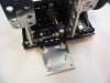
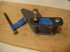
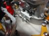
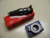
Ryan is about four inches taller than me; a possible dilemma in a car fit to a specific driver. To give us a bit of flexibility, an adjustable pedal mount was sought. With Fran’s good guidance, we tried a unit from CNC, Inc., San Diego, California. It raises the pedal assembly only a quarter of an inch. The base plate is made from a nice machined piece of aluminum. Centering it under the pedal assembly, we were able to find enough area to drill the mounting holes for the four slide bolts. To adjust the pedals one pulls it backwards and then replaces it in a different set of mounting holes. Simple, neat, and functional.
www.cncbrakes.com
Although the pedals could be adjusted to a comfortable position for me, getting enough forward travel for Ryan while assuring there was enough space for his size 11 foot to rest on the gas pedal was an issue. The clutch master cylinder extends back far enough that it interferes with the suspension bracket housing when the pedals are pushed forward. Some on line research (I cannot imagine this sort of project without the internet) revealed that Wilwood makes a smaller cylinder, “Compact Remote Master Cylinder”, part 260-7577, which has almost the exact same fluid volume. It is significantly shorter in overall length, giving more travel distance on the adjustable bracket. With this shorter master cylinder, the pedal assembly can be adjusted forward even farther than necessary to accommodate Ryan, so that a driver well over six feet tall with big feet should fit.
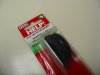
Getting the supplied hydraulic hoses to fit was a challenge, given the adjustable pedals and the need to push the pedal assembly forward to accommodate Ryan.. Although the straight hoses will work we decided to purchase three 16” hoses with a 90 degree fitting on one end. (Earls EAR-630117 16, from Summit). This resulted in a better fit on the clutch as well as the brake master cylinders and will minimize twisting when the pedals are adjusted fore and aft.
Ryan is about four inches taller than me; a possible dilemma in a car fit to a specific driver. To give us a bit of flexibility, an adjustable pedal mount was sought. With Fran’s good guidance, we tried a unit from CNC, Inc., San Diego, California. It raises the pedal assembly only a quarter of an inch. The base plate is made from a nice machined piece of aluminum. Centering it under the pedal assembly, we were able to find enough area to drill the mounting holes for the four slide bolts. To adjust the pedals one pulls it backwards and then replaces it in a different set of mounting holes. Simple, neat, and functional.
www.cncbrakes.com
Although the pedals could be adjusted to a comfortable position for me, getting enough forward travel for Ryan while assuring there was enough space for his size 11 foot to rest on the gas pedal was an issue. The clutch master cylinder extends back far enough that it interferes with the suspension bracket housing when the pedals are pushed forward. Some on line research (I cannot imagine this sort of project without the internet) revealed that Wilwood makes a smaller cylinder, “Compact Remote Master Cylinder”, part 260-7577, which has almost the exact same fluid volume. It is significantly shorter in overall length, giving more travel distance on the adjustable bracket. With this shorter master cylinder, the pedal assembly can be adjusted forward even farther than necessary to accommodate Ryan, so that a driver well over six feet tall with big feet should fit.
Getting the supplied hydraulic hoses to fit was a challenge, given the adjustable pedals and the need to push the pedal assembly forward to accommodate Ryan.. Although the straight hoses will work we decided to purchase three 16” hoses with a 90 degree fitting on one end. (Earls EAR-630117 16, from Summit). This resulted in a better fit on the clutch as well as the brake master cylinders and will minimize twisting when the pedals are adjusted fore and aft.
Attachments
Transmission Issues: the Joys of Car Building
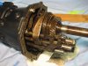
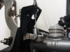
The Audi 016 transmission which we received was not particularly attractive. The entire unit was painted flat black, which clashed with the low gloss black and silver scheme used throughout the engine compartment. We opted to repaint it natural aluminum and low gloss black to match the engine.
On the side of the transmission is a cover plate for the shift actuating lever. As we were removing the three screws one inexplicably fell into the opening. We flipped the tranny over hoping it would fall out. No such luck. We spent an hour or more searching with a flashlight, probing with our fingers, but could neither see it nor feel it. When we rolled the transmission about, we could hear it clanking inside. The idea of that screw getting caught in the gears would not permit ignoring the problem. But having never been inside a transmission before, the idea of dismantling it was a bit intimidating.
A review of the repair manual at http://www.rrquattro.com/Audi100_GboxManual.html indicated the two halves could be separated without significant difficulty. The gears are essentially in the aft end. We removed the bolts securing the forward and aft halves and carefully separated the two. With a bit of poking around we found the wayward screw, clinging to a magnet located at the bottom of the housing below the right shaft, designed for catching metal fragments. The magnetic had done its job.
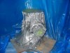
Taking advantage of the two halves being separated, the forward half was painted with natural aluminum engine paint and the rear half with low gloss black. A bit of silicone gasket sealer was placed around the mating surface and the two halves united again with shinny new bolts. The cable bracket and the shift mechanism was installed. Ryan spent a couple of hours cleaning and polishing the shift actuating lever cover plate. We have more work to do on the slave cylinder and related hardware, but that will wait for another day.
What should have been a couple hour project to paint the box turned out to consume most of a days time. But we won’t have to worry about a loose nut rattling around.
The Audi 016 transmission which we received was not particularly attractive. The entire unit was painted flat black, which clashed with the low gloss black and silver scheme used throughout the engine compartment. We opted to repaint it natural aluminum and low gloss black to match the engine.
On the side of the transmission is a cover plate for the shift actuating lever. As we were removing the three screws one inexplicably fell into the opening. We flipped the tranny over hoping it would fall out. No such luck. We spent an hour or more searching with a flashlight, probing with our fingers, but could neither see it nor feel it. When we rolled the transmission about, we could hear it clanking inside. The idea of that screw getting caught in the gears would not permit ignoring the problem. But having never been inside a transmission before, the idea of dismantling it was a bit intimidating.
A review of the repair manual at http://www.rrquattro.com/Audi100_GboxManual.html indicated the two halves could be separated without significant difficulty. The gears are essentially in the aft end. We removed the bolts securing the forward and aft halves and carefully separated the two. With a bit of poking around we found the wayward screw, clinging to a magnet located at the bottom of the housing below the right shaft, designed for catching metal fragments. The magnetic had done its job.
Taking advantage of the two halves being separated, the forward half was painted with natural aluminum engine paint and the rear half with low gloss black. A bit of silicone gasket sealer was placed around the mating surface and the two halves united again with shinny new bolts. The cable bracket and the shift mechanism was installed. Ryan spent a couple of hours cleaning and polishing the shift actuating lever cover plate. We have more work to do on the slave cylinder and related hardware, but that will wait for another day.
What should have been a couple hour project to paint the box turned out to consume most of a days time. But we won’t have to worry about a loose nut rattling around.
Attachments
Nice work as usual guys...
Fluid Reservoirs and Holes
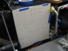
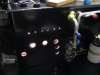
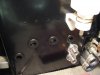
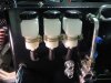
A template was prepared for locating the brake and clutch master cylinder reservoirs, heater water fitting, and electrical wire opening. The three reservoirs were lined up in the usual fashion, with the tops about a quarter inch below the top edge of the front foot well. By mounting the reservoirs on the right side a longer section of line was used to connect to the master cylinders on the left, which provided the necessary slack for adjusting the pedals fore and aft.
Grommets were used for each of the 3/8” hoses. A 1 inch hole saw provided a nice tight fit for the grommets. A PCV Valve Grommet, Help!/Dorman part number 42049, available at OReilly’s, Autozone, Advanced Auto Parts, and other car parts stores, works well. It accommodates the thick chassis material better than standard grommets. We have used a half dozen for both the hoses and the electrical harness in various locations on the chassis.
A 1 inch hole was drilled for passing the electrical wires in the lower right corner, making sure to leave plenty of room for the suspension bolt. Another grommet was inserted.
Each of the holes was dressed and the bare aluminum painted black. After the paint dried over night the grommets were inserted after wiping them with a bit of silicone lubricant to make them slide into place more easily.
We will soon complete the wiring, secure the AC lines, install the 1 ½” coolant hoses and add hose clamps to the hydraulic hoses.
Attachments
Air and Heat, Compressor Bracket
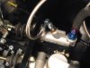
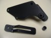
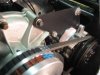
The compressor bracket provided by RCR arrived in several pieces. The idea is to have the parts welded locally due to the variations in engine builds. Not having welding equipment, we made up a jig and took the pieces to our local welder. He did a decent job. With a bit of grinding and shaping, followed by a coat of low gloss engine black paint, we hade a nice, sturdy bracket. It is a simple design but serves its intended function well.
The lower adjustment bracket is a simple flat piece of steel that fastens to a water pump bolt on one end and to the rear compressor bracket on the other. There was about a 7/8” mismatch because of our particular configuration, so we made two cuts in the bracket and had it welded back in place with the necessary offset.
A 40” belt fit perfectly.
The compressor was secured to the upper bracket with a 4 inch bolt and to the lower adjustment bracket with a 4 ½ bolt, utilizing the threaded fittings on the compressor.
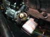
Before the compressor was installed for the final time, the oil pressure sending unit was installed. The supplied extension was not long enough to clear the compressor, given its more rearward location in our particular set up, so we purchased a second extension and a female coupling which places the sender out far enough to clear the compressor, engine and oil filter. (We will be installing a remote oil filter at a later date). No Teflon tape was used, since an electrical connection through the fitting is necessary.
The lower radiator hose was carefully routed between the compressor and lower pulley. It is a tight fit. We cut the end off of the same section of hose that provided the 90 degree right angle for the thermostat cover. (Part number D71281, from Advanced Auto Parts).
The compressor electrical connection required that a separate wire be run from the compressor to the trinary switch at the front of the car. This wire is not a part of the Painless kit. No relay was used in this circuit since none was recommended by Hot Rod Air.
The compressor bracket provided by RCR arrived in several pieces. The idea is to have the parts welded locally due to the variations in engine builds. Not having welding equipment, we made up a jig and took the pieces to our local welder. He did a decent job. With a bit of grinding and shaping, followed by a coat of low gloss engine black paint, we hade a nice, sturdy bracket. It is a simple design but serves its intended function well.
The lower adjustment bracket is a simple flat piece of steel that fastens to a water pump bolt on one end and to the rear compressor bracket on the other. There was about a 7/8” mismatch because of our particular configuration, so we made two cuts in the bracket and had it welded back in place with the necessary offset.
A 40” belt fit perfectly.
The compressor was secured to the upper bracket with a 4 inch bolt and to the lower adjustment bracket with a 4 ½ bolt, utilizing the threaded fittings on the compressor.
Before the compressor was installed for the final time, the oil pressure sending unit was installed. The supplied extension was not long enough to clear the compressor, given its more rearward location in our particular set up, so we purchased a second extension and a female coupling which places the sender out far enough to clear the compressor, engine and oil filter. (We will be installing a remote oil filter at a later date). No Teflon tape was used, since an electrical connection through the fitting is necessary.
The lower radiator hose was carefully routed between the compressor and lower pulley. It is a tight fit. We cut the end off of the same section of hose that provided the 90 degree right angle for the thermostat cover. (Part number D71281, from Advanced Auto Parts).
The compressor electrical connection required that a separate wire be run from the compressor to the trinary switch at the front of the car. This wire is not a part of the Painless kit. No relay was used in this circuit since none was recommended by Hot Rod Air.
Attachments
Throttle Cable
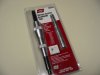
A nine foot stainless braid covered throttle cable was obtained from Lokar. Although long cables are not listed in their literature, they can easily fabricate them in one foot increments. We thought we needed eight feet, but ordered nine to be safe. It is a good thing we did. It was routed from the forward end of the engine to the right of the distributor, through the opening inboard of the left bulkhead, then along the left side of the drivers seat to the near the fire wall, where it looped around to the pedal assembly. A clamp was placed on the compressor bracket, which keeps the cable from interfering with anything, like a pulley or belt. Enough slack was present so the pedals could be adjusted fore and aft depending whether Ryan or Chuck was the designated driver. It turned out that the nine foot length was spot – on.
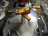
A bracket was fabricated from a 1 inch by 1 inch aluminum stock and secured on the right forward carburetor. An additional return spring may be added later, although the two springs already on the carbs provide a strong return force. The threaded fitting provided by Lokar matched the linkage perfectly. (This linkage is available from Inglese).
The Lokar cable worked well with the RCR pedal box. The hole on the frame was enlarged to clear the cable end fitting. The pedal arm was a bit too thick to clear the Lokar fitting, but a few minutes with the grinder solved that problem. This project went together well. The throttle operates smoothly.
A nine foot stainless braid covered throttle cable was obtained from Lokar. Although long cables are not listed in their literature, they can easily fabricate them in one foot increments. We thought we needed eight feet, but ordered nine to be safe. It is a good thing we did. It was routed from the forward end of the engine to the right of the distributor, through the opening inboard of the left bulkhead, then along the left side of the drivers seat to the near the fire wall, where it looped around to the pedal assembly. A clamp was placed on the compressor bracket, which keeps the cable from interfering with anything, like a pulley or belt. Enough slack was present so the pedals could be adjusted fore and aft depending whether Ryan or Chuck was the designated driver. It turned out that the nine foot length was spot – on.
A bracket was fabricated from a 1 inch by 1 inch aluminum stock and secured on the right forward carburetor. An additional return spring may be added later, although the two springs already on the carbs provide a strong return force. The threaded fitting provided by Lokar matched the linkage perfectly. (This linkage is available from Inglese).
The Lokar cable worked well with the RCR pedal box. The hole on the frame was enlarged to clear the cable end fitting. The pedal arm was a bit too thick to clear the Lokar fitting, but a few minutes with the grinder solved that problem. This project went together well. The throttle operates smoothly.
Attachments
Guys,
That bracket you have fabricated out of 1"x1" alloy looks a bit on the flimsy side compared to the rest of your throttle linkage parts, the right angle bend which the conduit is bolted to is likely to distort in use & cause premature cable wear & possible throttle sticking problems.
That bracket you have fabricated out of 1"x1" alloy looks a bit on the flimsy side compared to the rest of your throttle linkage parts, the right angle bend which the conduit is bolted to is likely to distort in use & cause premature cable wear & possible throttle sticking problems.
Transaxle, Flywheel and Starter
In a previous post, painting and prepping the transaxle was noted.
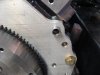
The flywheel, clutch, and starter were supplied by Kennedy Engineered Products. The parts were ordered and delivered within a few short weeks during spring, 2007, long before the car arrived, on the date they were promised. We were pleased with their service.
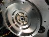
The pilot bearing was hammered into place. Once installed it protruded some distance, but the actual needle bearings were in a location where they would support the input shaft in the proper place, based upon careful measurements.
The flywheel, with its 28 ounces of balance, was secured with Grade 8 bolts, a bit of red Loctite and torqued to 50 pounds.
The starter motor was a bit too snug to slide into the adaptor place. A bit of filing on the lip of the starter helped slide it into position.
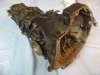
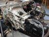
The slave cylinder and throw out bearing that were supplied with the transaxle were clearly original. We though it best to replace both. The pin securing the slave cylinder was hammered out. After removing the actuating rod the slave cylinder was vigorously hammered from the inside of the bell housing to free it. Twenty two years in the same spot had rusted it tightly into place. Once freed, the opening was cleaned out and the replacement temporarily installed. We obtained the parts from www.eGermanparts.com.
There are two small alignment bushings that MUST be placed on the backing plate when the transaxle is installed. Kennedy Engineered Products supplied the bushings. They serve to align the transaxle bell housing. The RCR backing plate has an appropriate detent which matches the bell housing detents. It was necessary to ream out the detent a bit on the RCR backing plate to get it to fit and even then it was very snug. The transaxle was test fit before the clutch was installed to assure it would mate with the alignment bushings and the pilot bearing, then removed, and the clutch was installed.
In a previous post, painting and prepping the transaxle was noted.
The flywheel, clutch, and starter were supplied by Kennedy Engineered Products. The parts were ordered and delivered within a few short weeks during spring, 2007, long before the car arrived, on the date they were promised. We were pleased with their service.
The pilot bearing was hammered into place. Once installed it protruded some distance, but the actual needle bearings were in a location where they would support the input shaft in the proper place, based upon careful measurements.
The flywheel, with its 28 ounces of balance, was secured with Grade 8 bolts, a bit of red Loctite and torqued to 50 pounds.
The starter motor was a bit too snug to slide into the adaptor place. A bit of filing on the lip of the starter helped slide it into position.
The slave cylinder and throw out bearing that were supplied with the transaxle were clearly original. We though it best to replace both. The pin securing the slave cylinder was hammered out. After removing the actuating rod the slave cylinder was vigorously hammered from the inside of the bell housing to free it. Twenty two years in the same spot had rusted it tightly into place. Once freed, the opening was cleaned out and the replacement temporarily installed. We obtained the parts from www.eGermanparts.com.
There are two small alignment bushings that MUST be placed on the backing plate when the transaxle is installed. Kennedy Engineered Products supplied the bushings. They serve to align the transaxle bell housing. The RCR backing plate has an appropriate detent which matches the bell housing detents. It was necessary to ream out the detent a bit on the RCR backing plate to get it to fit and even then it was very snug. The transaxle was test fit before the clutch was installed to assure it would mate with the alignment bushings and the pilot bearing, then removed, and the clutch was installed.
Attachments
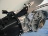
Clutch and Transaxle
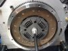
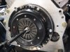
The matting surfaces on the flywheel were wiped clean of any contaminants with brake cleaner. The pressure plate and clutch were installed, careful to make sure the pressure plate was facing in the correct direction. A universal metric clutch alignment tool from http://www.sjdiscounttools.com worked well. The six clutch bolts were tightened alternately to avoid stressing the clutch and then torqued to 30 pounds using red Loctite.
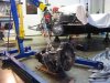
Using an engine lift made setting the transaxle into place a bit easier. It slid right in without difficulty. The six 12 millimeter bolts of varying length securing the transaxle to the backing plate supplied by Kennedy Engineered Products were secured. Be careful to use a shorter screw in the hole adjacent to the starter.
The clutch cables were temporarily connected. The transmission could be easily shifted through the first four gears, which made our day! Reverse and fifth did not work, likely because the reverse detent is missing. We are still searching for the parts to make the detent work.
A decent way to route the clutch cables will need to be addressed. Perhaps running both cables along the right hand side inside the cross brace would make a neater set up? Any thoughts??
The slave cylinder and clutch cable will be properly installed later. At that time final adjustments will be made.
The matting surfaces on the flywheel were wiped clean of any contaminants with brake cleaner. The pressure plate and clutch were installed, careful to make sure the pressure plate was facing in the correct direction. A universal metric clutch alignment tool from http://www.sjdiscounttools.com worked well. The six clutch bolts were tightened alternately to avoid stressing the clutch and then torqued to 30 pounds using red Loctite.
Using an engine lift made setting the transaxle into place a bit easier. It slid right in without difficulty. The six 12 millimeter bolts of varying length securing the transaxle to the backing plate supplied by Kennedy Engineered Products were secured. Be careful to use a shorter screw in the hole adjacent to the starter.
The clutch cables were temporarily connected. The transmission could be easily shifted through the first four gears, which made our day! Reverse and fifth did not work, likely because the reverse detent is missing. We are still searching for the parts to make the detent work.
A decent way to route the clutch cables will need to be addressed. Perhaps running both cables along the right hand side inside the cross brace would make a neater set up? Any thoughts??
The slave cylinder and clutch cable will be properly installed later. At that time final adjustments will be made.
Attachments
Similar threads
- Replies
- 25
- Views
- 3K