
Your toolbox is too small already hehe:laugh:

You are using an out of date browser. It may not display this or other websites correctly.
You should upgrade or use an alternative browser.
You should upgrade or use an alternative browser.
Marko's GTD (I think) 40
- Thread starter Marko Stefanac
- Start date
Hi guys,
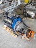
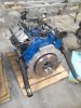
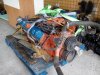
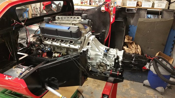
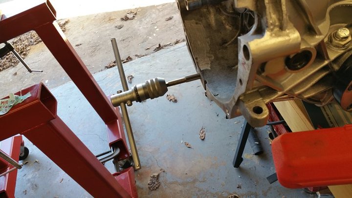
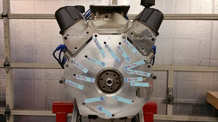
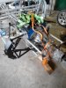
Finally got the engine home. Spent a few hours cuddling with it before doing any actual work.
As you can see, I was trying to marry the engine and the 01e after cleaning the gearbox. Still not happy with the cleanliness of the gearbox, gotta spend a few more hours on it and possibly paint it. Anyway, I got them bolted together however I do have a question for guys here that run the same setup. How many bolts did you fit between the engine and the adaptor plate and the gearbox and the adaptor plate? I think I got 5 through to the engine and 6 from the gearbox and that seems kinda flimsy. The tranny possibly has one or two more holes on the bottom end which I failed to notice since I ran outta workshop time. The plate aligns with the dowels perfectly so I think that's all good, but the rigidity of it all worries me.
Furthermore, one of the nuts on the oil pan prevents the starter to properly line up with the bell housing. I'll probably have to move that nut further away from the gearbox.
I brought some parts over to my machinist friend. After inspecting the welds on the rear uprights and finding they are porous like swiss cheese I decided to have him make me a new front plate. Also the five (?) mounting holes for the lower tie rods on the A arms meant that those plates are also out and another set of new front plates are going in.
It's nice to finally see some actual work being done apart from preparing the parts for assembly.
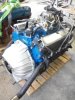
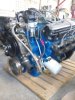
Btw, got the 302's big brother in, the 440 that's gonna live inside my '67 New Yorker from now on. The heaviest pig of an engine I ever saw. Luckily I now have the crane home too.
Cheers,
Marko
Finally got the engine home. Spent a few hours cuddling with it before doing any actual work.
As you can see, I was trying to marry the engine and the 01e after cleaning the gearbox. Still not happy with the cleanliness of the gearbox, gotta spend a few more hours on it and possibly paint it. Anyway, I got them bolted together however I do have a question for guys here that run the same setup. How many bolts did you fit between the engine and the adaptor plate and the gearbox and the adaptor plate? I think I got 5 through to the engine and 6 from the gearbox and that seems kinda flimsy. The tranny possibly has one or two more holes on the bottom end which I failed to notice since I ran outta workshop time. The plate aligns with the dowels perfectly so I think that's all good, but the rigidity of it all worries me.
Furthermore, one of the nuts on the oil pan prevents the starter to properly line up with the bell housing. I'll probably have to move that nut further away from the gearbox.
I brought some parts over to my machinist friend. After inspecting the welds on the rear uprights and finding they are porous like swiss cheese I decided to have him make me a new front plate. Also the five (?) mounting holes for the lower tie rods on the A arms meant that those plates are also out and another set of new front plates are going in.
It's nice to finally see some actual work being done apart from preparing the parts for assembly.
Btw, got the 302's big brother in, the 440 that's gonna live inside my '67 New Yorker from now on. The heaviest pig of an engine I ever saw. Luckily I now have the crane home too.
Cheers,
Marko
Attachments
Last edited:
Hi guys,
No progress being made as I had some issues with deliveries. Hopefully in a week or so I can start with the build.
Been working on my 300c thought I'll share a song I wrote for it.
Eating ozone at an alarming rate
With that muscle you love to hate
In a day he drains Kuwait
But never yet has he been late
Comparable to Boeing's weight
Wearing silver armor plate
Sideways screams this thirsty eight
Slaying trees is goddamn great
Cheers,
Marko
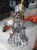
Still not happy with the cleanliness of the gearbox, gotta spend a few more hours on it and possibly paint it.
Here is mine, De-greased and painted.
How many bolts did you fit between the engine and the adaptor plate and the gearbox and the adaptor plate? I think I got 5 through to the engine and 6 from the gearbox and that seems kinda flimsy.
I drilled and taped the #14 and 15 to M10x1.75 and used all holes.
Hi guys,
Its been a while since my last post. First of all, thanks for that info about the plate. I will be doing the same. Btw great looking car you got there.
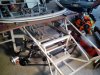
I have been finally making some progress. The front end, apart front the steering, is starting to come together. I will need some steeting rack extensions though. Even found some 17" wheels laying around that I can use for the time being. Rear end is still work in progress as I need to refabricate some parts but Im almost there. Once thats done I will be installing the sway bars and setting up the suspension. I decided to make new mounts for most, if not all, suspension parts. Radius rod will have adjustable mount for 4 or 5 different settings. After that Ill try lowering the engine in to see how everything fits together.
After reading some threads here I know some guys probably wont like this but I think its neccessary to spread the word when you experience something first hand. Ive been having problems with delivery from GT Forte. The whole thing has been going on from October. During that time Ive had two deliveries, both partially incorrect. For the last two months I recieved no replies to my emails. Mind you, I did get most of the stuff and I have a spare steering rack which I havent paid for, but Im missing the steering wheel boss and some other bits and the sway kit got delivered for the second time unfinished. Its not my intention to talk crap about people but I just wanted to point out the issue for future builders.
Ive been working on my New Yorker too and found out that in fact I have a Toyota rear end so if anyone has an 8 3/4" rear end laying around lemme know")
Thats it for now. I will post back once I make some more progress.
Cheers,
Marko
Its been a while since my last post. First of all, thanks for that info about the plate. I will be doing the same. Btw great looking car you got there.
I have been finally making some progress. The front end, apart front the steering, is starting to come together. I will need some steeting rack extensions though. Even found some 17" wheels laying around that I can use for the time being. Rear end is still work in progress as I need to refabricate some parts but Im almost there. Once thats done I will be installing the sway bars and setting up the suspension. I decided to make new mounts for most, if not all, suspension parts. Radius rod will have adjustable mount for 4 or 5 different settings. After that Ill try lowering the engine in to see how everything fits together.
After reading some threads here I know some guys probably wont like this but I think its neccessary to spread the word when you experience something first hand. Ive been having problems with delivery from GT Forte. The whole thing has been going on from October. During that time Ive had two deliveries, both partially incorrect. For the last two months I recieved no replies to my emails. Mind you, I did get most of the stuff and I have a spare steering rack which I havent paid for, but Im missing the steering wheel boss and some other bits and the sway kit got delivered for the second time unfinished. Its not my intention to talk crap about people but I just wanted to point out the issue for future builders.
Ive been working on my New Yorker too and found out that in fact I have a Toyota rear end so if anyone has an 8 3/4" rear end laying around lemme know
Thats it for now. I will post back once I make some more progress.
Cheers,
Marko
Attachments
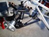
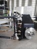
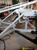
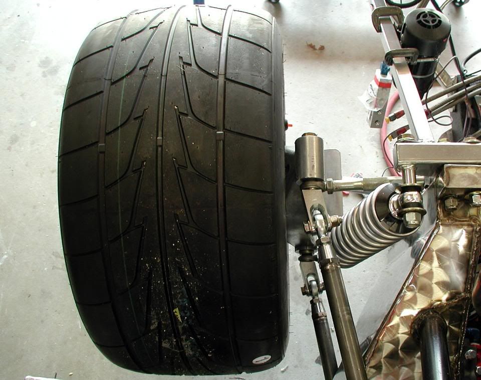
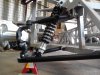
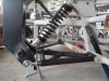
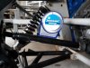
More progress! Ive been working on the rear end today. I will obviously have to make some changes to the mounting points but other than that it all seems to fit fine. If someone notices a mistake let me know.
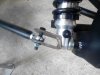
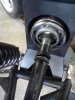
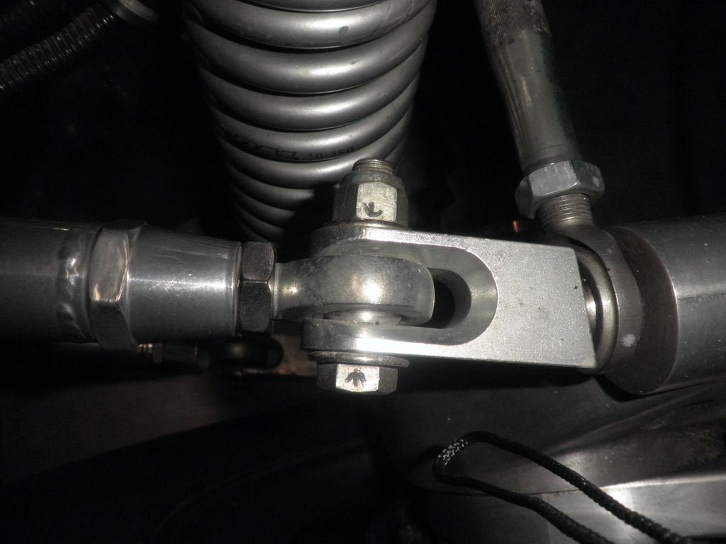
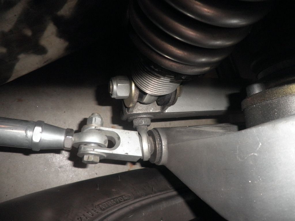
I did want to ask one thing. How did you guys sort out the space between the ball joints and the mounts? Simple washers seem like a bad solution since they will restrict the angular movement of the ball joint. Should I fabricate some sort of conical spacers that fit in between the mount and the ball joint? I presume the joints should be kept in there tight to prevent movement across the bolt. Also, the part where the shock, A arm and lower radius rod bolt together bothers me. I think it should have some spacers there as well.
I also ground off the steering rack mount cause it didnt seem right. I will make a new one. Found the extensions as well so thats sorted out.
All input will be much appreciated
Cheers,
Marko
Attachments
-
 IMG_20160219_135635.jpg90.2 KB · Views: 257
 -
 IMG_20160219_135643.jpg98.8 KB · Views: 241
 -
 IMG_20160219_135653.jpg93.1 KB · Views: 228
 -
 IMG_20160219_135714.jpg158 KB · Views: 239
 -
 IMG_20160219_135725.jpg78.3 KB · Views: 226
 -
 IMG_20160219_135745.jpg93.2 KB · Views: 239
 -
 IMG_20160219_135602.jpg106.2 KB · Views: 242
Hi Marko,
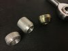
You should use conical bushes for spacing the rod ends. These can be sourced but if you have a milling machine, you can fabricate them by yourself. Best to use steel ones since aluminium ones with too sharp ends will be crushed at the conical side if made too sharp.
If you need an adress in the UK, let me know.
Regards
Andy
Marko,
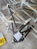
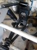
You are running into the problems i had /with my build. The rod ends at the chassis mtd. will use tubular steel rods to take up the space and make sure the rod end stays in the middle. Hard to see it in this pic but that is what I used.Will get some closeups for you when I get home.
On the other end you need to change the clevis that you are using. I used a solid piece of aluminum and the clevis fits snugly around the rod end. There is an angle on the face for it to match up with the axel housing. The arms are much thicker and may not need any washers at all. It will make sense when you see how it is done. Also your clevis if you stay with the ones you have, need to be facing with the open part facing up so it won't bind on the rod end.
 .
.
My shock tower has a bracket that it fits into and is not part of that bolt assembly at all and it is mounted inside of the axel housing to make the shock more vertical. will get you a better pic tonight.
Bill
You are running into the problems i had /with my build. The rod ends at the chassis mtd. will use tubular steel rods to take up the space and make sure the rod end stays in the middle. Hard to see it in this pic but that is what I used.Will get some closeups for you when I get home.
On the other end you need to change the clevis that you are using. I used a solid piece of aluminum and the clevis fits snugly around the rod end. There is an angle on the face for it to match up with the axel housing. The arms are much thicker and may not need any washers at all. It will make sense when you see how it is done. Also your clevis if you stay with the ones you have, need to be facing with the open part facing up so it won't bind on the rod end.
My shock tower has a bracket that it fits into and is not part of that bolt assembly at all and it is mounted inside of the axel housing to make the shock more vertical. will get you a better pic tonight.
Bill
Hi guys,
Both of your solutions seem about the same except maybe for the conical ends. Looks like it should work just fine.
Regarding the clevis, I like your solution Bill. Seems much more elegant and sturdy but it seems kinda tight in there too. Can the ball joint move freely inside?
The shocks on my setup are at a completely different angle. Did you go for the vertical to minimize bump steer or is there another reason?
One more question. Whit the car jacked up, what should be the position of the lower arms on the front end? I presume they should be horizontal but mine are tilted at an angle of some 15 degrees. If that is the case I will have to lower the upper ahock mount on the front end to straighten it out.
Thanks for the help guys, I appreciate it.
Cheers,
Marko
Marco,
There is room for the rod end to move a little, but then it isn't supposed to move much anyway. No washers are needed. The long bolt that goes throuth the upright goes right into the holder. The angle at the upright is parrallel to the upright so there is no bind on the camber support and the inside edges around the trailing arm rod end are ground down so that it does not interfere and allows a little more movement for the rod end.
The piece at the bottom is part of the suspension(A arm)and has the rod ends on it to adjust the toe.
The shock mtg. is the way the DRBs are built. It gets the pieces apart from other each other so that the bolts have one function and they are strongly built. Almost all of the replicas are tight at the top as the brackets are not very long. I have the QA-1 shocks and I would guess that a vertical position would have less travel/unit of compression than one at an angle. Those more knowledgeable than I could address that.
I was told by someone that the Australian roads are a bit rougher than are the U S roads, so they build stronger parts and frames. One of the reasons they weld steel panels on their space frames rather than aluminum rivets/panels. Adds a little weight, but with 550 hp or so I don't think it really matters.
Bill
Hi Bill,
I like the design and I get what you are saying about the amount of movement. The ends are actually only moving in the vertical plane as the upright goes up and down. Well actually its an arc but still, there is little or no lateral movement. The only lateral adjustment on radius rods come as a result from adjusting toe on the A arms.
I started thinking about your shocks and concluded that a) bump steer has nothing to do with shocks, b) my suspension knowledge is rather embaressing, c) having different mounting points for different things makes a lot of sense. I went out and bought a book on suspension building and set up. Found that I need to level the floor before doing anything else. Also, Ill take measurements of the chassis pick up points to make sure the chassis is straight and the pick ups are all in the right place.
Cheers,
Marko
Hi everyone,
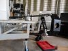
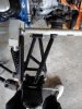
After reading the suspension book I now know words like parallelism, squareness, anti-dive and Ackerman angles and feel very good about pronouncing them in public. However I found myself in a bit of a pickle. My shock lenghts dont seem right (please restrain yourselves from dirty comments). I mentioned previously that the front lower wishbone is angled upwards and I now know this is completly wrong and that in fact it should be angled downwards so that when the full weight of the car is on the wheels the pickup points should be the same distance from the ground as the balljoint centre. I can achieve that with the longer shocks of the two. Also, rear A arm is parallel to the ground with the longer shocks which again doesnt seem right because when the car is lowered the springs will get compressed and the arm will pivot upwards around its pickup point. The shorter shocks just dont seem to fit anywhere without major pickup point relocation after which they would be angled a LOT. Also, the longer shocks have rose joints whereas shorter ones have rubber bushings which makes me think that the longer ones should be front to account for the anti-dive (!) setup. Ill include a few photos. Left hand side has short and right hand side of the car has long shocks. Your help is very much appreciated.
Cheers,
Marko
Attachments
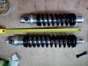
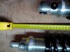
Here are two more photos of the rear end with longer shocks. I read somwhere on the forums that the shocks should be 14" front and 15" rear. My shorter shocks are only 11.8" long.
Cheers,
Marko
Cheers,
Marko
Attachments
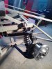
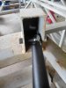
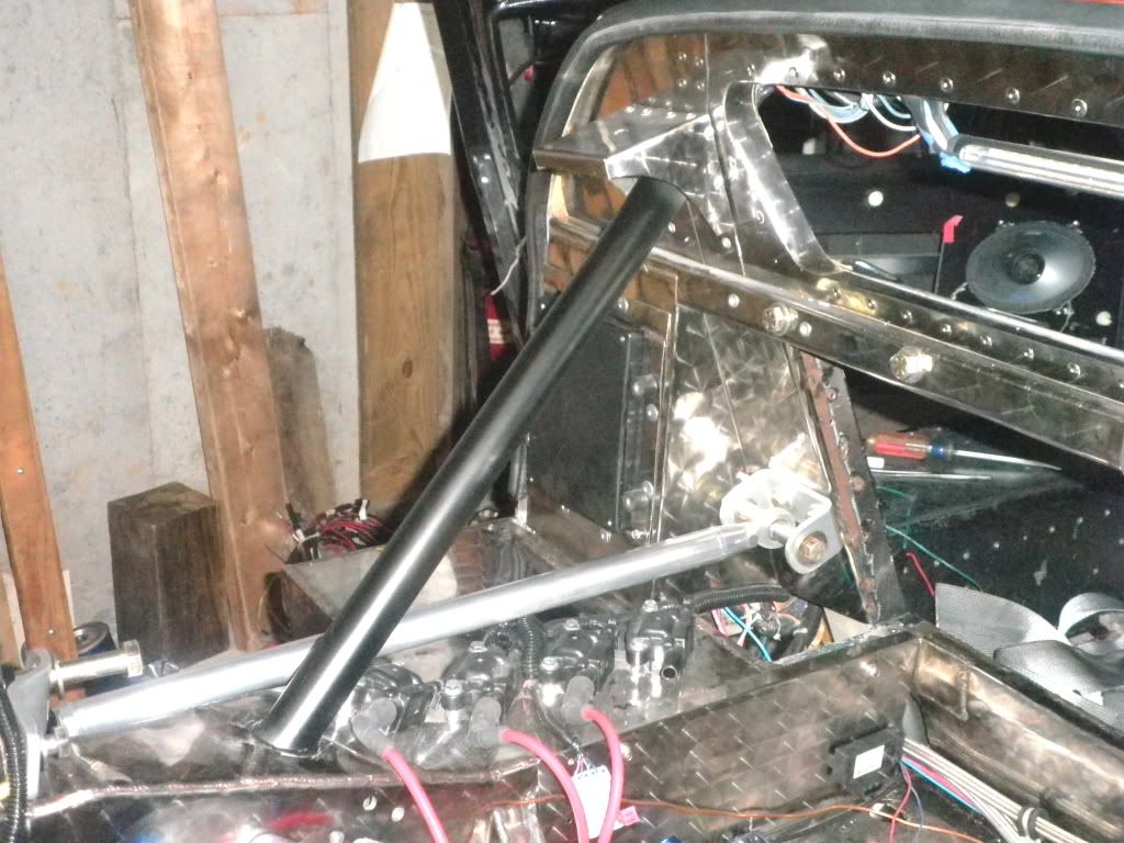
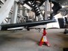
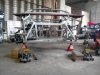
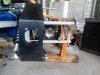
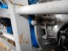
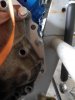
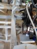
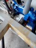
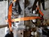
So, I wanted to test fit the engine and ran into yet another major issue. I dare to say biggest so far. There are serious clearence problems with the chassis, engine and gearbox and also a discrepancy with the position of the driveshafts in relation to the gearbox. The chassis rail is in the way of the oil filter but I might be able to sort that out by fitting a smaller oil pan and lowering the engine a bit. So I have another question. By how much can the driveshafts be angled? When connected its angled 10 deg in the horizontal plane and at least 15 in vertical. I may be able to knock off a degree or two but thats it. Ill attach some photos. Please tell me this is acceptable. Pretty please.
Cheers,
Marko
Cheers,
Marko
Attachments
-
 IMG_20160225_131458.jpg162.1 KB · Views: 216
 -
 IMG_20160225_131512.jpg141.2 KB · Views: 207
 -
 IMG_20160225_131519.jpg80.9 KB · Views: 210
 -
 IMG_20160225_131532.jpg96.8 KB · Views: 199
 -
 IMG_20160225_131547.jpg77.2 KB · Views: 184
 -
 IMG_20160225_131558.jpg188.4 KB · Views: 220
 -
 1456403543261-690301077.jpg153.8 KB · Views: 243
 -
 1456403564829-661472973.jpg102.5 KB · Views: 207
 -
 1456403586297205953643.jpg125.2 KB · Views: 284
Hi Marko,
Should the rear of the engine block be in front of the horseshoe? Can the engine be moved forward?
Should the rear of the engine block be in front of the horseshoe? Can the engine be moved forward?