

You are using an out of date browser. It may not display this or other websites correctly.
You should upgrade or use an alternative browser.
You should upgrade or use an alternative browser.
Roaring Forties 105
- Thread starter Jim C
- Start date
RF105 upgrade parts
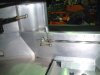
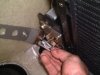
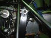
Reverse action shifter .
This really came about because redoing the rear linkage is not always the best option.
This shifter is going into a car in the next week or so to see if it holds up ok.
The clamp plate on the front rose joint allows the hole unit to rotate on the shift shaft axis.
But allowing the shaft to go back when the stick is pushed forward.
This puts 1st gear back in the across & up position.
Attachments
Last edited:
RF105 upgrade parts
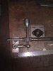
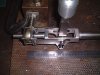
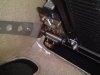
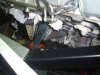
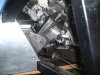
I did get all the hinges with the car but Im not using them.
I dont like the way thay look & I think it would be silly to assume that you wont want to take the front & rear clips off to work on the car.
When I designed these I kept in mind that you dont want to lose the body position as that seems to be a major issue.
If I pull either clip off I dont want to spend 2 hours resetting the body gaps.
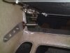
Basicly the hinge plate & body plate never comes off the car so it will always end up in the same spot. all 316ss.
The pics show the steps off removal.
It takes about 1 min .
Rear hinges are similar but havnt finished them yet.
I am also working on a door hinge as a quick release along simalar lines.
I have worked on a few gt40s now & find the doors to be painfull in a workshop situation.
My shop is not that big.
I did get all the hinges with the car but Im not using them.
I dont like the way thay look & I think it would be silly to assume that you wont want to take the front & rear clips off to work on the car.
When I designed these I kept in mind that you dont want to lose the body position as that seems to be a major issue.
If I pull either clip off I dont want to spend 2 hours resetting the body gaps.
Basicly the hinge plate & body plate never comes off the car so it will always end up in the same spot. all 316ss.
The pics show the steps off removal.
It takes about 1 min .
Rear hinges are similar but havnt finished them yet.
I am also working on a door hinge as a quick release along simalar lines.
I have worked on a few gt40s now & find the doors to be painfull in a workshop situation.
My shop is not that big.
Attachments

Last edited:
RF105 upgrade parts
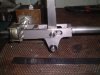
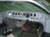
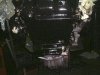
Last shot .
Again 316ss
Most off the work is s/steel.
One thing I realised early is by the time I get it laser cut in steel,sand blast it powder coat it ,then it closes all my tolerances up so then I have to spend time filing all the holes out it works out much cheaper to do it in s/steel.
Plus it is stronger.
Again I dont wish this to look like a for sale section but I think these are a pritty good product & if anyone is intererested email or PM me.
I hope to have my site & banner up soon.
Jim
Attachments
Last edited:
G’day Jim,
A lot of great idea’s mate.
There are several things during my build that I have thought could do with modification and improving but time constraints have meant that these changes will have to happen later. It looks like you are addressing most of these issues, which is great news. Now we now where we can obtain the aftermarket upgrade components with little or no pain.
Keep us updated with your progress.
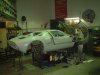
I havnt posted in a while so I will update.
I have had the car 3 years and I feel I should have finished it that’s why I don’t post .
Did a lot of suspension homework to get to this point.
Made arms 75mm longer, made new uprights from tube.
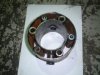
Doing this and using a modular bearing has reduced the scrub radius down to 13mm from over 100mm.
The upper and lower arms have a rose joint as the ball joint.
This is allowing for more neg adjustment if required.
The lower arms I made nylon bushes instead of the urethane, they were fiddley to make as they had to be size for size and required grease nipples fitted but they don’t have the binding effect.
I have had the car 3 years and I feel I should have finished it that’s why I don’t post .
Did a lot of suspension homework to get to this point.
Made arms 75mm longer, made new uprights from tube.
Doing this and using a modular bearing has reduced the scrub radius down to 13mm from over 100mm.
The upper and lower arms have a rose joint as the ball joint.
This is allowing for more neg adjustment if required.
The lower arms I made nylon bushes instead of the urethane, they were fiddley to make as they had to be size for size and required grease nipples fitted but they don’t have the binding effect.
Attachments
The off set of moving all the scrub radius and wheel offsets ect is the Ackermann has been reduced a lot.
I have not done my measurements yet but I know it has some but not what I would like.
TUFF
I have learnt a lot doing this part of the car.
If I was to look at suspension I see things that I would not have fully under stood before.
I know I would not put the rack in the spot that this one is.
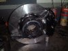
I can understand it suited the original upright but to get the scrub radius reduced you start to push the upright into the wheel and the disk gets closer to the steering arm.
Flatter disks help but this becomes an issue with wheels as the callipers move to the outside of the wheel and is likely to hit.
But if the rack is behind the wheels and high it helps with a lot of clearance problems giving you the chance to have the Ackerman that you choose not what you are left with..
The steering arms are removable and I can change the ratio if I wish.
I ended up with about .004” bump steer
The top arm at the outer ball joint can be spaced to change the roll centre height.
I have not done my measurements yet but I know it has some but not what I would like.
TUFF
I have learnt a lot doing this part of the car.
If I was to look at suspension I see things that I would not have fully under stood before.
I know I would not put the rack in the spot that this one is.
I can understand it suited the original upright but to get the scrub radius reduced you start to push the upright into the wheel and the disk gets closer to the steering arm.
Flatter disks help but this becomes an issue with wheels as the callipers move to the outside of the wheel and is likely to hit.
But if the rack is behind the wheels and high it helps with a lot of clearance problems giving you the chance to have the Ackerman that you choose not what you are left with..
The steering arms are removable and I can change the ratio if I wish.
I ended up with about .004” bump steer
The top arm at the outer ball joint can be spaced to change the roll centre height.
Attachments
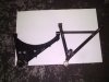
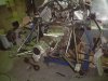
Got away from the A lower arm as it was giving a fair amount of rear bump steer.
This was fixed by going to the 2 lateral links on either side.
This has reduced the rear bump steer to .003” toe in at 0 deg caster.
I moved the upper link from the front to the rear on upright.
Felt this may change things as it goes through arcs.
It had no effect on toe in bump ect ect.
It has given more clearance at the rear shock and also at the roll centre adjuster.
I understand about 3 and 4 element rear suspension (amount of pivots) and it has leant more towards 4 elements.
But it has made it closer to the bottom arm.
It is all rose jointed and does work smoothly.
Attachments
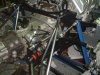
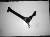
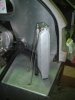
The roll centre adjuster was fiddley but I think it was worth it.
I made the stool out of on piece then made the appropriate brackets to suit.
I installed another crush tube in the frame to give me 2 mounting bolts with the ability to move up or down.
To stop the load laying the stool over I linked the L/H to the R/H via the bar.
The bar has an adjuster to change the rod length as it goes up the rod goes out.
The adjuster links (rose joint) also takes some of the sideways load on the mount but also making for accurate equal adjustment from left to right.
Finding an equal starting point is easy for the roll centre as both stools have a datum hole in the back, it is a matter of just screwing a bolt through them and the frame.
Then do equal turns of the adjuster to set roll centre.
Attachments
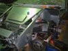
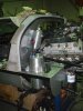
I cut the rear off the frame , (mainly looks) I made 2 frames to mount the rear clip hinges onto.
I made the trans mounts in a more forward position as the frame was gone.
I made a new member between the shock towers.
The crossmember under the sump I cut out and made removable this way I can remove the engine sump if I require.
Made engine mounts.
This is a big engine,
They say they are a nice engine it would want to be, I read somewhere
it weighs 590lbs the 302 was 500 , it big to fit it makes the exhaust a tight job it doesn’t look period so it better do the business or I will be disappointed.
Attachments
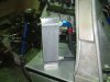
Dry sump tank I made out of 2 spun halfs that would fit in the battery space.
Made an oil air separator that plumbs back to the sump.
The charcoal canister fits in the space next to the tank.
Also made the water surge tank.
Mounted oil cooler
Made an oil air separator that plumbs back to the sump.
The charcoal canister fits in the space next to the tank.
Also made the water surge tank.
Mounted oil cooler
Attachments

Similar threads
- Replies
- 139
- Views
- 18K