Engine Orientation in a '40

Keith

Moderator
Engine Orientation in a \'40

Guys, I have a question which is related to another thread, but i don't want this to get bogged down in drift (I reckon you'll now guess which thread I'm refrerring too!)

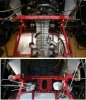
In relation to the upper and lower rear suspension attachment points, where EXACTLY does the motor/trans joining point lie? Does this placement vary between different chassis designs? I have tried to get a view on this through photos on the site, but parallex makes this difficult. An overhead view would be ideal however. I am trying to get a handle on the chassis stiffness/support problem, and have thought of a possible solution depending on the answers. Please bear with me. /ubbthreads/images/graemlins/smile.gif
 
Re: Engine Orientation in a \'40

Hi Keith -

In relation to your question about suspension point location - this might help. Picture shows chassis rear on Roy's modified GTD. The yellow line shows where standard chassis member normally passes and white shows sus arms.

Note that Roys engine is also forward a little too (50mm?)as the lower rear crossmember normally fouls part of the gbox/bellhousing which prevents the box being lowered much.
 

Attachments

  • 56345-keithrsgtd.JPG
    56345-keithrsgtd.JPG
    77.1 KB · Views: 503

Keith

Moderator
Re: Engine Orientation in a \'40

Hey paul, thanks very much for those photos and the trouble you must have gone to to get them. If this installation is typical, then my "brainwave" is not an option. Quite simply, I was going to suggest the use of an ali engine "plate" of say, 1/4" thickness which mounted between the engine and gearbox, suitably cut out for same, with allowances made for extra length input shaft shaft etc, notched to locate on frame rails and bolted to horse collar. In drag racing, we used such a plate mounted at the front of the engine (in a front engined configuration) suitably cut out for ancilliaries, which anchored the motor firmly to the chassis rails forming a solid tie together with solid engine mounts in the appropriate location and triangulated shock tower/firewall bracing. This provided the very best resistance to torque induced twisting moments on launch. If you can see where I was coming from vis a vis the '40, if the engine/trans joint was close enough to the chassis suspension pick-up points, then such a plate would bear much of the transient loads induced by both engine torque and suspension effort without unduly stressing the motor itself and "solidifying" the entire drive train/suspension package. This may have solved a problem for the chassis lacking in a lower cross brace in order to gain a lower motor placement. Unfortunately, I have not been close enough to a '40 for some considerable time, so I was unable to do more than simply "theorise". Thanks again for your time. Back to the drawing board! /ubbthreads/images/graemlins/crazy.gif
 

Howard Jones

Supporter
Re: Engine Orientation in a \'40

OK how about between the gearbox and the bellhousing? Would require a "little" machine work to both faces.
 

Keith

Moderator
Re: Engine Orientation in a \'40

If that point was very close to the suspension pick up points then yes in theory, but I think the loads may be too much for the gearbox. Mounting the plate between engine and bellhousing would be much stronger, so that the mass of the engine at it's widest point would resist torsional loads. In theory, this makes the engine a "semi-stressed" member, but in practice (bolted at the other end in a front engined configuration) it worked fine with 600-700 hp violent launches. Of course, even in a conventional '40 set-up, the motor is secured at 2 points to the chassis, and if you use the solid as opposed to bushed mounts, you are already transmitting any chassis flex to the motor AND the gearbox anyway and vice versa. The engine "plate" would take most of these loads making a much stiffer drive train. But, it's academic because it appears that the engine/bellhousing location is too far aqway from the suspension pick up points, unless you want to lengthen your '40 by a foot!
 
Re: Engine Orientation in a \'40

Keith,

Summit Racing sells engine torque links(Competition Engineering) for Mustangs($54.95 each), that might be adaptable for what you are trying to accomplish.
Adjustable and easily removable, by pulling a couple of pins(for smoother road use). Attached from the rear of the heads to each chassis rail, they would provide a pretty solid link across the chassis.


Bill
 

Attachments

  • 56408-cee-4010.jpg
    56408-cee-4010.jpg
    11.4 KB · Views: 373
Re: Engine Orientation in a \'40

Bill,
If you look close at the first pic of Roy's setup, you will see just such a link from the #7 cylinder across to the oposite side in front of the shock tower. No????
Bill
 
Re: Engine Orientation in a \'40

Bill,

Si senor! /ubbthreads/images/graemlins/grin.gif Very similar!

Roy's car is primarily a track car though. The pin removable links might be better suited for mostly street/occasional track use(like our cars).
I like my kidneys too much to mount a permanent one!


Bill
 

Keith

Moderator
Re: Engine Orientation in a \'40

Blimey! A good old fashioned turnbuckle no less! Looks effective too. The (theoretical) idea of the solid plate interface between engine and bellhousing is that it would lock the drivetrain together with the frame at the exact point where the suspension pick up points impart loads to the chassis, thus eliminating chassis flex, whilst allowing the motor to be mounted lower, without the need for a lower sub-frame in this area; the lack of which (in some designs) is causing some controversy elsewhere on this site. Unfortunately, the orientation of the engine/trans assembly with the suspension pick up points (as ably demonstrated by Pauls' excellent photographs) does not seem to support this theory.
 
Re: Engine Orientation in a \'40

Bill - you're correct, the brace was fitted to reduce lateral movement when hard on/off the gas - Roys 40 is used on track 90% of the time with the occasional road test too. It is a bit harsh for long journeys, but great fun for short ones! /ubbthreads/images/graemlins/grin.gif (& bloody LOUD inside)

Keith - I suspect this '40' is what you refer to (sort of) - the motor mounted to a 0.5" thick alloy plate at front (pulleys poked through plate) and the rear of the engine also bolted to a fixed plate across the chassis. A neat trick was the suspension all mounted on the gearbox - made it light too.

Another of Mr GTDs (RC) creations /ubbthreads/images/graemlins/grin.gif
 

Attachments

  • 56428-bulkheadmotor.JPG
    56428-bulkheadmotor.JPG
    133.3 KB · Views: 515

Keith

Moderator
Re: Engine Orientation in a \'40

Indeed Paul, that is exactly what I'm talking about, although .5" seems a tad excessive. Belonging to the Barnes Wallis school (if it won't break, it's too strong/heavy) I would have thought that 1/4" plate would have been ideal as there presumably would be no bending loads on said plate. Getting back to my original comments, a motor so mounted at or near the rear suspension pick-up points, could possibly solve the potential problem of chassis flex where a lower crossmember cannot be fitted for motor mounting height reasons?
 
Re: Engine Orientation in a \'40

Hi Keith - 0.5 may seem a bit thick - but I seem to remember that the plate was being used 'structurally' too, so to speak and the chassis was very light around it. It certainly accelerated well from what I recall when I drove it and with a 'cooking motor' so it must have been light.. /ubbthreads/images/graemlins/smile.gif
 

Keith

Moderator
Re: Engine Orientation in a \'40

Crikey! Just realised what I was looking at!! Inboard shocks > pushrod? Gearbox used as "stressed" member (with a cage)? Now you're talking! What happened to this arrangement? Is this not practical for your average '40? /ubbthreads/images/graemlins/tongue.gif
 
Re: Engine Orientation in a \'40

Keith
Exactly what I was thinking. There is some real thinking outside the dots going on there.
Paul
What happened to that car?
 
Re: Engine Orientation in a \'40

If any of you have access to a Porshe Carrera GT(get to know your shop forman) you can see the arrangement. Quite simple really. Just have to think about how you want it laid out(the shocks that is).

Bill
 
Re: Engine Orientation in a \'40

Keith,

I came across this car on a visit to the factory in Poole a number of years ago. It was in the yellow roadster 40 of Ray Christophers - AKA Hairy Canary if I am right. Unless changed since its still competes in the UK now.

Paul,
When I saw Roy's car at Brighton the link was shorter and ran from N/S head to N/S shock mount, is the link pictured the new or old arrangemnet?
 
Re: Engine Orientation in a \'40

Hi Keith -

I wondered when the penny would drop! - Ray has always been one for innovation - and this system caused quite a stir when debuted in the Isle-of-Man in 1999. Im not overly sure the scrutineers knew where to look first....

Anyway - it performed well, surviving a fairly large knock at the 'goose-neck' on the big Lherghy-Frissel hill climb (see below). He couldn't continue though as a suspension arm bent (track rod end held!). I believe Ray still has the car somewhere - or thinking about it, he might have used some major parts in the current spyder. The suspension had been done before on his R42, which also had inboard shocks with push-rod actuation. I remember when we were removing the engine for a rebuild, we unbolted what seemed 'just a few bolts' and then wheeled the trans away complete with wheels, susp, driveshafts etc etc - very cute!

By 'cage' I assume you mean to transfer load from one side to other at rear suspension points - YES it did, all very light though...

Dave - you are correct too - the picture posted was an older version and the brace does now go to the n/s turret.
 

Attachments

  • 56494-rayouch.JPG
    56494-rayouch.JPG
    26 KB · Views: 421

Keith

Moderator
Re: Engine Orientation in a \'40

Hi Paul. Fantastic info and it's got me thinking. I just love this kind of innovation and you have to wonder whether Ford would have gone this route anyway had they continued development of the '40. It's certainly changed my view as to what is possible in either space frame or mono config. and has opened up new possibilities for my forthcoming build. Thanks again for the info/pictures.
 
Re: Engine Orientation in a \'40

Hi Kieth, a lot of the questions you have may only be resolved once you have decided on which engine/gearbox/type of chassis you would use. Certainly the choice of transaxle would have great impact on how you would mount it, a ZF is installed very differently than a Renault or an Audi box, and the Porsche different again. The most prolific box used in the UK up till now is the Renault, and whilst this is a very good unit it has weaknesses that say the ZF has not, but the ZF is heavier etc etc. I believe in getting the C of G as low and forward as possible, and to achieve that we have reduced the chassis length by supporting the Renault boxes much like the ZF, with the box predominantly supported from the beam crossing over the box on the axle line, with just some lightweight supports further back to absorb stresses on the casing. See the pictures of Andrew Fordyces GTD40 chassis for detail. This support does several things in one, including carrying the major weight of the engine/gearbox, preventing any longitudinal and rotational movement of the unit, and allowing for the very low mounting position, still with a cross member between the lower suspension pick up points. The chassis to the rear of the axle line can therefore be very much lighter, carrying only the rear clip mounts. Frank
 

Keith

Moderator
Re: Engine Orientation in a \'40

Thanks for the info Frank. I'm certainly of the opinion that there is much to be gained by looking very closely at the configuration of the rear chassis in terms of c.g. and suspension mounting points. It's info like this from those in the know which is leading me away from current "production" style chassis and more into a custom build scenario, especially as I have mainly competition use in mind...
 
Back
Top