Aerodynamics question

I saw it mentioned elsewhere that the SL-C starts getting lift over the top at around 120mph and that the placement of the radiator duct pushing air over the top reduced that lift.

I’m no supercomputer, but air is air and the flow over the camber of the cockpit seems like it’s going to produce lift/low pressure regardless, and I was thinking of modifying the radiator outflow somewhat like others have done and directing it to go to each side and keep the outflow and heat away from the high pressure area against the windscreen.

All that said, I’m not planning to race, but I’d rather not introduce instability if I change my mind.

Any aerodynamics people want to chime in?
 

Joel K

Supporter
Jeff,

Check out the thread below. Scott did some real modeling I found very interesting…

 
Thanks, Joel, I’ve seen that analysis and will be incorporating the formula for entry/exit sizes as much as I can. I do note that it is mentioned that moving the outlet is at the cost of downforce, not sure I understand why other than relocating a source of high pressure over the nose, but nothing about lift generation.
 

Scott

Lifetime Supporter
Jeff,

Moving the outlet forward doesn't necessarily reduce downforce. Look at most cars with an outlet in the nose (including all of the serious race SL-Cs) and you'll note that it's forward of the stock SL-C location. My comment regarding downforce in the aforementioned thread was that the La Ferrari-style airfoil in the duct reduced drag at the cost of downforce because it reduces the vertical component of the air exiting the radiator. If you force all of the air exiting the radiator upwards you will increase downforce at the cost of increased drag. This is no-brainer trade off on any SL-C that isn't running a massive splitter like the Superlite Race Splitter which is essentially an upside down wing with end plates. The more vertical the airflow the more downforce up until the point where you decrease mass airflow which would decrease cooling and downforce while also increasing drag.
 

Scott

Lifetime Supporter
I forgot to mention that you can also add a Gurney flap which to reduce the pressure above the radiator outlet. This will also increase downforce at the cost of increase drag. It could be a simple piece of metal or something molded into the nose like the picture below:

1658583514810.png


The above molded flick was designed by an aerodynamicist using CFD. The objective was to maximize mass airflow through the radiator up until the point of diminishing returns (i.e., that the increase drag wasn't a sensible tradeoff).
 
Thanks for the deeper explanation, Scott. I think what my plans are for the outlet will likely reduce downforce in favor of redirecting the hot air to the sides.

In your exploration of aerodynamics did lift over the car become a factor?
 

D. Nye

Lifetime Supporter
j7.PNG

Although not a SLC the photo of the 1967 J7 car is clearly showing what Ford was trying on the radiator discharge in front of the windshield. Pre Dan Gurney flap?
 

Scott

Lifetime Supporter
D. Nye,

I'm no expert, but let me make the following three points:

(1) I'd be careful looking at any single picture of a race car because teams learn and adjust. For example, looking at the Mercedes side pods at the beginning of the 2022 season would send you down the wrong path. A more tangible example is the SL-C that won the national championship. The first is picture would leave you to believe that the stock location of the outlet was ideal. However, the second picture is a later version and shows a complete rethink.

1658596602898.png

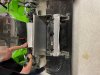
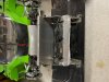
Early version appears to maintain the outlet's stock location and size. Note the large Gurney flap (black piece of metal sticking up 90 degrees from the nose. Completely appropriate for a race car, but not particularly nice on a street car.

1658596939733.png

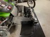
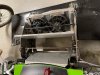
Updated version. The outlet is much larger and moved forward. There is an internal duct to guide all of the air upwards. Look at the angle of that duct and it is seems pretty clear that they were using it to generate downforce. Also note the three cutouts in left fender under the top vents to allow air to escape from the wheel well. Not shown is the massive wing with endplates that replaced the old splitter.

Note that the male buck for the SL-C was designed and constructed in clay. To my knowledge, there was no CFD performed until much later when they were chasing the national championship. To my understanding the primary outcome of the CFD was the change in the radiator duct/outlet and the Race Splitter (not to be confused with the Track Splitter which some people run on the street). The pictures below were taken from the Superlite website. The first picture shows a high pressure zone directly on top of the the stock radiator outlet which is intuitive. The second picture shows a rethink (I have no idea if it's the one that they wound up building). It looks like the vertical component of the radiator outlet flow clears the roof scoop (my CFD model indicates that the roof scoop generates a fair amount of lift).

1658598390557.png


1658598836888.png

(2) Every car is different and engineering is a game of tradeoffs. If you don't understand what their objectives and constraints were you might misinterpret things. Looking at that car, the windshield looks more raked than the SL-C's and less likely to create a high-pressure zone at the trailing edge. However, most importantly, the leading edge of the outlet is moved well forward of the stock SL-C location and the shape of the internal duct could easily be changed to move the trailing edge of the outlet forward. Would that help? I don't know and my guess is that they probably didn't either.

(3) We (as in other people) know a lot more about aerodynamics today that we did in 1967. My guess is that there wasn't enough computing power in the world to run a rigorous CFD model back then even if the software had existed. Much of the learning came from comparing CFD, wind tunnel and real-world data over the last 50 years.
 
Last edited:
The primary goal is to get high pressure air (the source of which is the high pressure air caused by vehicle velocity that has to be forced into the front of the car for cooling purposes) away from the under surfaces of the car. The high pressure air under a vehicle is the primary source of front end lift for street cars. This air can be under the belly pan or under the front bodywork (hood/bonnet, wheel arches primarily). Most street cars do not have hood vents due to front engine configuration. I do have hood vents on my C5 track car which does help expel some of the high pressure, but it is relatively inefficient since there is no way to duct the radiator to the hood due to the engine. You will also see wheel arch vents in serious track cars to extract these areas of high pressure under the bodywork.
As far as hood vent location, you want to vent the radiator to the area of lowest pressure on the upper surface of the hood. The highest area of pressure is at the transition of the hood to the windshield, it would be a bad idea to vent to this area in any situation. Flow through the radiator is based on the differential of the pressure in front of the radiator vs the pressure behind it. So you want the vent to exit the hood in the area of the lowest possible pressure, usually at the front 1/3 to mid hood. Ducting to an area of higher pressure decreases the *delta* pressure, resulting in poorer flow through the radiator which can have significant engine cooling implications. The key is ducting the airflow before and after the radiator to prevent the high pressure air from finding itself under the bodywork and inducing lift.
The biggest contributor to front end lift in homebuilt cars like the SL-C, GTM, etc is failure to duct the incoming air tightly to the radiator, the ducting the air from the radiator tightly to the hood, which falls on the builder since neither kit manufacturer offers this option. No big deal up to highway speeds but critical beyond that.
Then you can get into discussions about radiator inlet and exit sizes, front splitters, underbody airflow, and rear diffusers (yes, rear diffusers can contribute to significant downforce in the front 1/3 of the vehicle if you shape the underbody correctly!).
 
Last edited:

Ted

Supporter
I am working with Agile Automotive on redesigning the front section of my SL-C. I recently visited Fran at the Superlite factory to take a look at what he did with their SU National Championship winning car for ideas. Here's some pictures of the redesign on Fran's car:
 

Attachments

  • S1.jpg
    S1.jpg
    453 KB · Views: 187
  • S2.jpg
    S2.jpg
    472.3 KB · Views: 178
  • S3.jpg
    S3.jpg
    457.3 KB · Views: 174
  • S4.jpg
    S4.jpg
    459.3 KB · Views: 173
I'll add my 2-cents based on practical experience with the SLC. My radiator outlet is trimmed slightly larger. No flap. Nose is WELL sealed around the radiator. Street splitter. Fender louvers.

With the CF wing mounted above roof height... Car has a bit of a push at 150+. With wing at real low AOA, rear is planted. Car seems to have no lift as above 130 or so it bottoms much easier and at 160+ It's more or less scraping all the time (country highway [closed for those who care]). That is with 850f/950r springs.

With the wing removed (Texas mile), car is skittish. Not un-safe, but a big change. Have to roll into the throttle until well past 125mph. Makes the turn at the end or the runway comfortably at 150 once used to the feel wo the wing.

I've switched to a much smaller wing and at some point will use a bigger splitter.
 

Fran Hall RCR

GT40s Sponsor
On the race car we run Penske 8760 shocks with 1150 front and 1300 rear springs.
Bigger full race splitter
same wing as we sell in carbon, high mounted but with swan neck mounts

Driver feedback was always how planted the car felt...even through uphill sections like the climbing Esses at VIR
 
Back
Top