Bob's EV SLC Build Log

At long last I can start a build log for this project. The idea has been building for just about two years now, serious planing for about a year. I went back and forth as to which platform to do this build on, the SLC or the Ultima. I was able to get very good scans of both chassis, and both have advantages and disadvantages, but in the end the SLC will be easier to converter to AWD, and it is much more readily available in the US. I have been trying to acquire a used, wreaked, or incomplete SLC for over a year with no joy. I finally pulled the trigger last month and bought Mel's unfinished kit. I go to pick it up next weekend. I have been collecting the EV motors, batteries, controllers, contractors, charges, ect. for the past year. Most of it is now acquired, and its time to start. I will probably take a sabbatical from work in the fall to focus full time on the build through the winter. I am located just outside of Boston, so if anyone wants to stop by as we get rolling let me know.

I think this is the first EV build thread on the forum, and the second EV SLC to my knowledge. I think it will have a number of other firsts along the way.

The plan is to build a full EV SLC, AWD with about 1,280 kW (~1700 hp) peak power and 1550 Nm (1144 ft-pound) torque with a 64 kWH battery pack providing ~200 mile range (in range mode), in a package below 1590 kg (3500 pounds). It will be gear limited to about 275 mph. I know it is not going to be lite compared to most builds here, but it is svelte for a EV.

The build list of main components is as follows, I know a lot of this might not mean too much to non-EV people, but I am going to include this information for future builds.

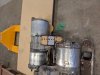
Batteries: 24 pacifica LG-Chem cells (6s4p configuration) They will just fit in place of the old gas tanks, and engine bay. Will be enclosed in a Kevlar/carbon fiber box with aluminium subframe. Batteries will be glycol cooled via heat exchanges.

BMS: 4 x Orion

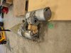
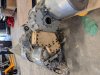
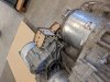
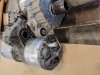
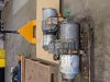
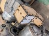
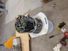
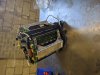
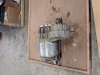
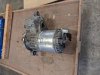
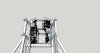
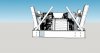
Motors Rear: 2 x Tesla LDU Base model, each geared to 4.5:1, locked diff, w/ external oil pump and custom sump. This gearing gets the torque per wheel slightly under a 1.5-1.8 friction coefficient tire can handle. Significant modification will be needed to allow fitment.
Motor Front 1 x Tesla LDU Sport-Performance, geared to 4.5:1, LSD w/ reverse internal pump.

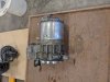
Motor Controller: Right now 3 x VCU 2.0 from Advantics, if AEM can get there new VCU 300 to drive the tesla inverters any time soon I will switch to it. Was going to go with the open inverter platform, but recently was persuaded to avoid it. Still going to test it, as i have a board already.

MCU: (Main Computer unit) Basically this is a Can-Bus controller, that will provide touch screen control for almost everything on the car. Polykup makes it, I have not purchased this yet, but it looks very nice.

DC-DC converter: Tesla Model S

Contactors: Custom, each string of the batteries will have its own fuse and contractor.

Cooling: Right now the plan is to retain the stock radiator and location, and cool everything on a single loop, however this may change to a a 2 loop system, one for the motors, and another with active cooling for everything else. In the later case side/rear mounted ac condensers will mounted.

Traction control: GPS/Wheelspeed based Racetronics unit. However if the AEM system becomes available this will not be used.

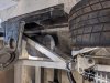
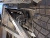
Front suspension will be modified to a push rod, and shock will be mounted right above the front drive unit. Will be sacrificing about 4.0" of foot well to the drive axles.

That's the broad strokes. Ill post drawings and photos as they become relevant. I may do a youtube series on it, but I really just don't think I'll have the time to do one of quality.

Bob
 
Exciting times Bob! Welcome to the club of SLC builders and kudos to you on such an ambitious build. I for one will be eagerly anticipating your updates.

Traction Control: I was surprised to see that you will need a dedicated traction control since I thought that the main motor controllers would have this capability built in.
 
On the traction control. Tesla drives are all open diff, and they use a brake based traction control unit. There are open source inverter boards that can be installed into a Tesla invert and allow one total control over all parameters, some have used this to add indrive TC. However, much like tuneing a IC motor, it can be very hard to get that perfect performance. Tesla has their drives very well optimised, and I don't want to lose that, nor do I really have the experience needed to do more than use others people settings for the drive.

In my setup I will be using 2 Tesla drive units in the rear, one for each wheel, but gearing them way down. They put out so much torque stock a single wheel could not take the traction. The front end will be a single drive with the open diff replaced with a LSD unit. The traction control system technically should not be necessary if I did my math right and use appropriate tires, but with this much torque..any EV's are near underivable under full power without it.

A stretch goal is to add inertial senors and allow for torque vectoring of the rear two wheels. I may also build a throttle mixer which should allow real time front/rear power distribution control. But all this is gravy. First thing is to get the all the batteries and and drives mounted.

Bob
 

Randy V

Moderator-Admin
Staff member
Admin
Lifetime Supporter
It all sounds like a great plan - however, you may want to reconsider your use of an LSD in the front drive axle. From my experience in the offroad world, the LSD brings with it a TON of understeer when at the limits of traction. I have to believe it would be much the same in a pavement situation at the limits of traction. The difference being that you would likely be going much faster on pavement..
 
So this is something that we have talked alot about. The original plan was to do 2 small Tesla drives up front, but I just can't fit them in. The slc I have scans of at least has the center chassis rail off set to the passenger side. It makes fitting 2 drives very tough. The single large drive is a real compromise, but it will make the build alot easier.

That said the LSD is not going to be absolutely necessary if the traction control system is solid. I have not used the system yet and just going by the vendors assurances. On the Tesla a similar system is amazing. Alot of the issues with LSD and FWD come from geometry issues with drive shafts. We will be using same length shafts with a lay shaft on the driver side. I looked into getting different offset rims for the front, but that will be something I looking into more once I have the car in person to get better measurements.

Thanks for the input

Bob
 
good luck bob! i follow your build with curiosity and admiration. I keep on working on my project (1 rear ludicrous motor at the back/16 tesla batt modules in tank and engine compartment) every day. To gain some weight i will use a main ''charger + dc dc converter'' in one (liquid cooled/108A) sold by stelthEV. Single loop cooling for motor + batt using existing radiator on the SLC. Fran confirmed to me he already packaged in CAD the motor; the motor sits behind the chassis and the axis align well (i don't know how he succeed and curious to discover when i visit slc) so apparently no need to extract the inverter. I don't know if you are interested but i found a nice 400V AC compressor and electric brake from tesla (no vaccum pump/15A draw max) and how to wire it, i m currently building a traction control (arduino module) but will only work for 2WD.
fred
 
Yeah I have had the car at my warehouse for a couple weeks now. It was dusty, but all there. Pretty much un-touched for 9 years, some surface scrapes on the front air dam, and on some of the body panels, but nothing major. I sat in it for the first time, and it is much more roomy than I thought it would be. I think I will have the room in the foot-well I need. I am adjusting the models I have to fit real life, seeing if I can really get all the batteries in. The models were a very close fit to the real thing, but the batteries I have are just a really tight in the models, and when I place them in the car in real life....the clearance between the frame and posts is really tight, even with a carbon fiber battery box its going to be challenging to assemble the battery. I have a half crazy idea to build my own battery for it. Not much more expensive and about 60% of the weight, and fitment become a non issue, and much easier to keep the weight centered and low to the ground. The down side is assembling a battery that can theoretically put out 9000 amp @ 400V for a few seconds, it starts to get real very fast.

Fred--You can fit a drive in the rear space the transmission sits in, but you get a pretty steep angle on the half shafts going to the uprights. I will post some sketches. I know the rear shafts are good for > 22 degrees, and i would say it is close to this. There is an another issue alot of the guys that are doing conversion with single large performance units are seeing, and it is why I went with dual base models gear up to 4.5:1. The performance large drive, to get the 646hp /1400 amp output puts the motor into mode where it creates more heat than it is able to transfer to coolant. Above about 1000 amps it seems these drives begin to overheat, and you have about 15-20 min of driving before they have to stop and let them cool down. There is a very good thread on a tesla swap into a cobra kit car, and even with aggressive cooling they are running up against the inherent heat transfer of the drive unit. For street driving you would probably not find conditions where you push this envelope, but on the track it is a real issue and limits the cars performance. The common fix seems to be to dial back the power on the drive, kind of defeating the purpose of putting in the high power drive.

The base models only put our 950 amps, and don't seem to have cooling issue to the same degree, and at 4.5:1 a single drive puts out just about the amount of torque a single drag radial or track tire on a 3000 pound car and handle. The down side is you really need to mount two to get the performance. How I have it sketched up, i have almost a straight shot from the drive output right to the wheel hub, but its going to take some really interesting mounts to get everything in.

Ill start posting photos soon, just haven't had the time to setup a folder and transfer all the car images to it.
 
Your infos are priceless. Fran wrote to me the axles align well so i believe he has a chassis modification ready for that motor (good for me). Of course it s different for you has you have already the car. The solution i have for the heat is eventually to use the two rear air intake either to make a single loop with 3 radiator (+PWM fans eventually) or 1 loop for the batteries using front radiator and another loop for thr motor using the 2 rear radiator. A back up solution is to use a liquid/liquid exchanger with ice (the same they use on Z06 to cool down the compressor). As it s a really easy modification to do i will probably perform a '' do and try'' and see how it goes. My goal is avoid cooling problems on 5 laps (maximum allowed here in qatar for non carbon ceramics brakes). To my point of view the dual motor setup is definitely for drag race. On a ''normal racetrack'' you don't really take advantage of it and it s better to look for lightweight. There is one exception: your setup where a crazy amount of energy is available. You make me hesitate on my own setup because of the batteries. These LG are light and cheap and will fit easily on 2P6 config but i makes cooling more complex and capacity is really small (i want to be able to make 2 sessions of 5 laps without charging) I still have a few months before final choice.
 
So the cooling problem with the large drive pushing "performance +" mode is not about cooling the transfer fluid, glycol/water, better. Guys are running ice boxes on their glycol loops for short races and measuring the temp rise as it passes through the motor, and still only get 2c changes in a pass, while the motor climbs 15-20c per lap. The issue is two parts, one how the drive is designed the other how the coolent flows through it.

The first problem is the more difficult to fix. The drive on has coolent flowing through the outside of the rotor and the out side of motor case. The windings must dump heat through the air gap and into the rotor. This is the weak spot. The large drive is only rated at 35 kw continuous or 90 kw for 15 min. Basically at 90kw you will heat soak the drive to overload (180c I think) in 15 min,coolent flow rate or temp minimally effects this. Guys are getting 150-200 Kw on the track from them, but they heat soak and the drive start dropping power by the end of short 15-20 min race.

TLDR; Large drive units w/ performance upgrade are great for short bursts of amazing performance, but they can't sustain it. The sad part is you go through all the work to get a 1600 peak amp HV system in place and you can only do a couple short pulls with it before the drive starts self limiting.

What I don't think anyone has fully figured out is if the heat is solely from the current or a combination of current and friction heating from the air. People have had some success with liquid N2 and Co2 injection to cool the windings. If friction heating of the air is significant, pulling a vacuum on the drive might help. Works on our centrifuges at the lab, but I don't know if the motor case could take the vacuum without bending/failing.

My solution to the problem is to just add more mass, kind of like using larger brake rotors. Double the mass, you can absorbe more heat before fade. If I can sustain 300 kw for 25 min without the drives dropping power, I will consider it a success. I may look into compressed gas cooling.

The other issue the the coolent flows from the drive to the inverter in these units. If the inverter gets above 85c it shuts down. Here good cooling systems really help. If you have big radiators keeping the coolent at 60-70 is not a big deal. Some people have reversed the flow path, going inverter to drive, others have put the drive and inverter in separate loops. I will probably do the later, but it is technically not necessary.

What I haven't seen is how ambient temp effects this. I don't know how hot Qutar gets, but I bet if your already 10c higher than most places, you coul assume your window to heat soak is just that much smaller.

Bob
 
Your infos are priceless. Fran wrote to me the axles align well so i believe he has a chassis modification ready for that motor (good for me). Of course it s different for you has you have already the car.

I did not realize he was modifying the chassis for you. If so I can think alot of changes that would make it fit very well. It will be interesting to see what he does. If you get images please post them.
 
This is awesome. I've been seriously considering doing something similar with my extra SL-C chassis and will be following this with great interest.
 
I did not realize he was modifying the chassis for you. If so I can think alot of changes that would make it fit very well. It will be interesting to see what he does. If you get images please post them.
I will keep you updated as soon as i have more infos (and pictures of course). I m waiting to go there but it s too complicated for me to travel at the moment. Thank you very much for your infos once again. I m reading every of your post carefully.
 
Got the first part of the motor subframe designed. see the pictures below. I have been wanting to try out slot and tab fabrication techniques for some time. This seemed like a perfect application. The tolerances on the slots are .5 mm, and the parts went right together. Welding them up will be not issue, I haven't decided to use stainless or not, the price is not that much more. The part are all designed in sketchup against a 3d scan of the tesla drive. This part is a 2 axis mount that attaches the two drives to each other. The subframe will have two of these in it. The final part will be out of .25" steel, laser cut. I had the part test cut out of .25" MDF from a online laser shop. Had the part in my hands in 24 hours from submission, pretty amazing. Part fit perfectly, first try. I just hot glued that pieces together. In one photo I show the opposite side of the drive units and you can see how the motor mounts align to each other.

In the photos below the tesla drives still have the inverters attached (the ends with 2 ports for the DC wires), I will be pulling them off this weekend, once I build a table that holds the drive on their side so I can work on them.

Now that this part is done, and I am confident of the design process using the drive and chassis scans, I will be sending the full subframe out to be cut from MDF to test fitment. After that, it will take a week or two to get the parts in steel.
 

Attachments

  • IMG_20200813_145141.jpg
    IMG_20200813_145141.jpg
    466 KB · Views: 800
  • IMG_20200813_145145.jpg
    IMG_20200813_145145.jpg
    484.3 KB · Views: 778
  • IMG_20200813_145149.jpg
    IMG_20200813_145149.jpg
    448 KB · Views: 761
  • IMG_20200813_145153.jpg
    IMG_20200813_145153.jpg
    463.1 KB · Views: 733
  • IMG_20200813_145200.jpg
    IMG_20200813_145200.jpg
    498.4 KB · Views: 761
  • IMG_20200813_145207.jpg
    IMG_20200813_145207.jpg
    504.6 KB · Views: 744
  • IMG_20200813_145247.jpg
    IMG_20200813_145247.jpg
    369.7 KB · Views: 856
Last edited:
Short update. Pulled the inverters off the drives. No real issues, thankfully there are some videos of people doing it on youtube, helped to make sure I didn't miss any bolts. Oddly, there is not a "how to" video, but just click bait videos, "look's what inside a tesla!", but it helped to see people bust in and break stuff. I has going to make a table with a hole in it so I could put the drives on the side, but harbor freight was out of the carts I was going to use. When I open the transmsion case to change the gear ratio and add the locked diffs, I will have to build one. The dives are really a awkward to move and balance. For removing the inverter a 30L PE bucket worked fine. I attached the pictures below so you guys can see how small the drive becomes without the invert attached. I also test fit the inverter in the frame. I knew it would fit, but it is neat to see it on the frame where it is going to live after all this time of thinking about it.

Had to modify the subframe design because of the lip on the drive from where the invert mount. It is about a 1" over hang, i had planed for 0.5". The clearance is so tight that half inch really mattered. Design is done now, I just have to add the tabs and slots. With luck I'll be testing fitting the full MDF subframe this weekend.
 

Attachments

  • IMG_20200817_175050.jpg
    IMG_20200817_175050.jpg
    400.7 KB · Views: 766
  • IMG_20200817_175241.jpg
    IMG_20200817_175241.jpg
    429.8 KB · Views: 707
  • IMG_20200818_120134.jpg
    IMG_20200818_120134.jpg
    363.8 KB · Views: 696
  • IMG_20200818_120343.jpg
    IMG_20200818_120343.jpg
    430.7 KB · Views: 695
  • IMG_20200818_120349.jpg
    IMG_20200818_120349.jpg
    471 KB · Views: 687
  • IMG_20200818_120354.jpg
    IMG_20200818_120354.jpg
    460.8 KB · Views: 822
  • MVIMG_20200817_175108.jpg
    MVIMG_20200817_175108.jpg
    321.5 KB · Views: 808
Bob, that's soo cool! Thanks for sharing the pictures and your journey.
I'm completely new to EV drivetrains, but your efforts motivated me to investigate and educate myself.
What kind of modifications do you need to make on your tesla drives, that requires you to open up the 'electronic' heart? I was expecting you to mod the Dif, but what expecting that to be only on the gearbox section of this drivetrain. What am I missing?

Keep the info coming.. before you know it I'll have my own EV conversion in the workshop :D
 
So I am running the inverters not attached to the drives. The inverters will be in the location I show in the photos, one inverter per side. Removing the inverters allows me run two drives in the rear, to center the mass perfectly over the rear axle line, and lower it in the chassis to an absolute minimum. There is just not enough room in the existing chassis design for it with them on. I will be running the drives "upside down" and inclined from horizontal. This allows you to but the heaviest part of the drive and the lowest point in the frame. A AU time attack racing team did this configuration, and it seems to work well. Like inverting the Porsche transmission, I will have to do some physical modification to the transfer case. The AU team uses a electric pump for lubrication, and runs what could best be called a dry sump for the transfer case. (I think) I plan to do the same. Tesla has switched to electric pumps now on the drive units. Other than that while I have the the transfer case open I will swap to the 4.5:1 gear ratio from stealth EV and a locked diff for each drive.

The only electrical modification I may do will be to use the open inverter projection inverter control board. This would allow total control over the inverter and motor. While it sounds attractive, there are conflicting reports if you are capable to get the drive as well tuned as tesla has it. Also, the project has continuing supply issues for the hardware, so it might not best choice. I may eventually shift over to it as the project evolves.

I will have to run 3 HV AC lines to motors from the inverters, jumpers for the sensors, and come up with electrical sealing solutions for the inverter and drives, all will be 3d printed to fit. A company in NH has adapter plates for the motor and the inverter to give you the mechanical and cooling hook ups for the units. They are early prototypes, but they have installed them on at least one other vehicle.

Other than fitment and lowering the CG, splitting the inverters from the drives will allow me to run the motors on their own cooling loop. I should be able to pre-chill the motors, maybe even to sub zero temperatures, to extend the time before heat soak performance degradation on race days. Pre cooling might get me another 10 mins before you hit saturation. I envision external hook-up for a -40 C chiller, and then maybe onboard active cooling with electric AC compressors for the drives. For street driving, I do not think pre cooling or active cooling is really necessary, you are not going to be able to sustain 100-150 kw per drive very long, there just isn't that much open road anymore. And on the track, active cooling doesn't really get you anything as you will be into heat soak almost immediately, and you only need to drop the drive about 2C every 3-5 min, which is what they can transfer max the to coolant. A small radiator can handle that. They can take very high temp, but just degrade performance as they heat up. As previously stated, the bottle neck is not cooling the transfer fluid, its heat removal from motor windings. Above about 30 kw output the motor begins heat soaking. The drive inverters, DC/DC inverters, the charging units, and the BMS will all be on the same cooling loop, holding it between 4 and about 55 C. I will probably use the existing radiator for this loop.

If I was to start a R&D project for this drive it would be some kind of cooling for the motor winding. I'm sure tesla has already thrown $$$$ at the problem, but maybe there is a solution that works for a performance car over a mass market car. I suspect injecting nitrogen or high pressure (3000 psi) compressed air into the drive would help, but it would only work for a short time until the bottle is dry. I need to run some thermo calculations for heat removal via adiabatic expansion. It might get another 1-2 C per time period out of the drive. I think I could get widen the performance window significantly on these drives with some simple tricks.

Bob
 
I'm in MA, right outside Boston. Just sent the subframe design out for MDF prototype. Here are some mockups of what went out. I really wanted to see what could be done with slot and tab design. The angle on the uprights was a real pain to work with, but I think I have the whole assembly to fit and mount to the frame well. It bolts to the rear, at the wing mount points, the front frame rails like the ls does, and then attaches to the top cage in 4 places. The attachments to the top cage will use the tie rod setup like the regular kit uses. The top cage is not shown. I got inspired by a Mr. Strickland who designed and built a full aluminum monocoque frame for a first gen Lamborghini inspired kit car, the Chupacabra. He has a a youtube series on its design and construction. Whole frame is slot and tab, and glued together with structural adhesive. This was a learning experience, as I have another project that will have a full frame design for a 80's pulse autocycle I am converting to EV.

I should have the cut mdf friday or sat.
 

Attachments

  • subframe final top.jpg
    subframe final top.jpg
    164.8 KB · Views: 757
  • subframe final right.jpg
    subframe final right.jpg
    185.8 KB · Views: 798
  • subframe final rear.jpg
    subframe final rear.jpg
    169 KB · Views: 744
  • subframe final left.jpg
    subframe final left.jpg
    141 KB · Views: 745
07605805-FAEB-4EA0-BA98-869AF7B3001A.jpeg

Autocycle now we’re are talking. Just got this one was a dealer demo up by boston. I’m down in CT good amount of SLCs around here bit no EV ones, why I was thinking about going that way.
 
Back
Top