Bob's EV SLC Build Log

MDF prototype came in. What a pain the workflow was. Fusion360 has a real issue exporting DXF files for laser cutting. Had to manually edit them in adobe for single cut lines. Real adventure.

But, fits like a glove. A couple pieces need slight modifications, but I'm going to aluminium and steel next week. Pieces are not bolted in place, so sitting a little low in the rear.
 

Attachments

  • IMG_20200903_002019.jpg
    IMG_20200903_002019.jpg
    440.9 KB · Views: 629
  • IMG_20200903_002007.jpg
    IMG_20200903_002007.jpg
    499.4 KB · Views: 662
  • IMG_20200903_002051.jpg
    IMG_20200903_002051.jpg
    456.9 KB · Views: 586
  • IMG_20200903_001947.jpg
    IMG_20200903_001947.jpg
    473.8 KB · Views: 601
  • IMG_20200903_002130.jpg
    IMG_20200903_002130.jpg
    446.2 KB · Views: 579
  • IMG_20200903_002927.jpg
    IMG_20200903_002927.jpg
    409 KB · Views: 629
Couple more shots of the subframe on the motors. I haven't removed the inverter from one of them yet, but I had to make sure I could get frames in to the units, and that everything was aligned. I need to add a couple access holes for nuts, but it looks ok.

Going to cut a few parts more out mdf, and the go for it. Then start on the front motor mount.

Is there a login to to access the build manual? Realized mine didn't come with a manual.

Bob
 

Attachments

  • IMG_20200904_235502.jpg
    IMG_20200904_235502.jpg
    441.6 KB · Views: 572
  • IMG_20200904_230205.jpg
    IMG_20200904_230205.jpg
    514.9 KB · Views: 548
  • IMG_20200904_230213.jpg
    IMG_20200904_230213.jpg
    480 KB · Views: 558
  • IMG_20200904_230228.jpg
    IMG_20200904_230228.jpg
    491.7 KB · Views: 597

Joel K

Supporter
Great work on the build, I am enjoying following along. Very interesting to see how you are mocking up the mounting system. Never seen those prototype pieces done that way before.

If you contact RCR, they could provide access/login info to the manual.
 
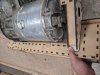
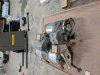
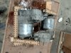
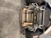
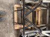
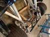
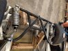
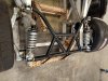
Yeah it's not they way I have done it before either. But the clearances where so tight, the semi-symmetric design, and the with the number axis i had hit just made sense to try something new. Plus with 3d scans of the motors and chassis available it was a logical choice. The cost of laser cutting metal has dropped too, I can probably get the whole frame and motor mounts for about 800$. That is really cheap compared to water jet or CNC. I have seen alot of RC guys do similar construction techniques for drones and planes in wood, GRF, and carbon. One turned me on to this (attached) paper on slot and tab design and strength analysis for metal construction and it all kind of clicked. Plus, if anyone else wants a subframe, or wants to tweak the design for use in something else, copies are very easy. Where as if I one off-ed a subframe as I have done before, making another is almost the same amount of work.

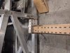
These slots are all 0.2 mm tolerances on the tabs, and it makes for a really tight fit without glue. It is near the limits of the laser cutter for accuracy, especially and the curves. And with riv-nuts and other interesting fasteners, in not sure you absolutely even need to machine the parts at all anymore. Just cut, weld (or glue!), add your hardware, and install.

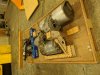
But this is kind of what I am doing this project for. It really is a prototype for techniques and ideas I have been playing with for some time. I could have just built a by the book (what ever that is) SLC, but I hope to push the envelope here. Wait to you see the battery design....nothing like it in the automotive EV space yet.
 

Attachments

that a lot of work there! but amazing! I recently review my project as it may turn into a race car (that has to be efficient for 5 laps only). So i keep the original design 1tesla rear drive. In order to gain some weight i may switch from tesla batt to LG chem batt (2p6 config) and 2 loops cooling. however the LG chem seems not be availabler anymore (look like LG want to supply only manufacturers). i hope you already have your batts or have an alternative solution. Still waiting for customs athorization to import and planning my trip to RcR in october (can t wait to discover fran's package to set up the tesla motor within the frame). good luck and once again congratulations for your ambitious project
 
I have a set of LG chem's, but I am going to use them on a different project, a pulse autocycle i picked up. Going with a custom battery here, kind of like alot of electric motorcycle guys are building. Trying to link up 4 strings of LG chems was just going to get to costly with battery management, and getting it all to fit was going to a real compromise. Getting 12 in there will be no issue for you.. I know someone that might have 6 or 12 still if you are interested. I am doing another round of MDF prototype right now, after bolting this one all together I needed to make a number of small changes, and I wanted to see it all in real life before I spend the money on metal.
 
Fusion360 has a real issue exporting DXF files for laser cutting. Had to manually edit them in adobe for single cut lines.

I use it all the time. Have had exhaust flanges, trans adapter (Graz to 1UZ), steering wheel all cut. Just make a drawing from the 3D and exported the drawing as DXF.

My laser/water jet shop has always been happy with the files.
 
I have a set of LG chem's, but I am going to use them on a different project, a pulse autocycle i picked up. Going with a custom battery here, kind of like alot of electric motorcycle guys are building. Trying to link up 4 strings of LG chems was just going to get to costly with battery management, and getting it all to fit was going to a real compromise. Getting 12 in there will be no issue for you.. I know someone that might have 6 or 12 still if you are interested. I am doing another round of MDF prototype right now, after bolting this one all together I needed to make a number of small changes, and I wanted to see it all in real life before I spend the money on metal.
That s fantastic bob! i m definitely interested for 12 of them if they are in a good condition/ low age/good voltage/ good price otherwise i may have to stick to the tesla ones. Thank you very much for the information. Here is my email for the seller: [email protected] I keep you updated
I m flying to Superlite factory on october 23rd to finalize everything and already took appointment with Fran there.
i will research a bit on customs batteries as well to see how much it would cost to build a 400v/50kw batt for my project.
 
I use it all the time. Have had exhaust flanges, trans adapter (Graz to 1UZ), steering wheel all cut. Just make a drawing from the 3D and exported the drawing as DXF.

My laser/water jet shop has always been happy with the files.

Yeah so when I looked at the fusion360 output dxf files in adobe they looked fine to me. However the company I am using, ponoko, flagged them all as having double line weights. Basically the laser would cut everything twice is how they explained it. The same files on my friends cheapo Chinese cutter had no problem. I just got the second prototype back from them and I used sketchup this time for the output with a slightly different work flow and they all went trough with no issues. I must be doing something wrong in fusion that is causing it.

anyhow, here some pictures of the v2 subframe with the motors in it and the frame mounted on the car. Does anyone know why phots are rotated when I upload them?

Also, my car car came with some missing fasteners, its looks like they where removed and just lost over time, or I can't find them in any of the boxes i got. One are the rear base shock mount bolts. Is there are parts list or for these or is it just measure and order from fastenal? Is there a bolt quality people have settled on?
 

Attachments

  • IMG_20200926_231541.jpg
    IMG_20200926_231541.jpg
    434.6 KB · Views: 504
  • IMG_20200926_231600.jpg
    IMG_20200926_231600.jpg
    394.9 KB · Views: 502
  • IMG_20200926_231634.jpg
    IMG_20200926_231634.jpg
    437.8 KB · Views: 500
  • IMG_20200928_131657.jpg
    IMG_20200928_131657.jpg
    448 KB · Views: 502
  • IMG_20200928_131703.jpg
    IMG_20200928_131703.jpg
    421.3 KB · Views: 506
  • IMG_20200928_131711.jpg
    IMG_20200928_131711.jpg
    393.2 KB · Views: 479
  • IMG_20200928_131726.jpg
    IMG_20200928_131726.jpg
    431.5 KB · Views: 498
  • IMG_20200928_131737.jpg
    IMG_20200928_131737.jpg
    426.1 KB · Views: 530
So now that the rear mounts for the motors are done, and out to metal fab, I am coming back to look again at my front end sketches, and trying to fit a drive in up front. The issue is you need to open up a fairly large hole in the firewall to fit the drive through. On par with the size of the extended foot well. My original plan was to go with a push rod front end, and move the steering rack up ideally ~2 inches (although I could get away with 1") to make room for the motor to clear. Can anyone comment as how much moving the rack up 1-2" will effect steering performance. It will increase the tie rod angles, and all that comes with that. The thing is I have never driven one of these, and I don't know what the base case is. How much bump steer is acceptable. I know there is alot of adjustment in the the steering arm, how much and in which direction do most people adjust the rod end at steering arm? On my car, the tie rods just clear the edge of the rim, maybe .25" clearance at full lock. Raising the rack would add about 6 degrees to the tie rod angle, and about 1" at the edge of the rim at full lock. If I where to raise the rack, I would need non linear tie rod ends, decrease turning radius, or modified steering arms. The last two are not things I really want to dive into, as it starts to radically change the steering geometry. Has there ever been discussion around rack location? I searched the forums, but most of the discussions are around rack selection and travel length.

All is on the table at this point.

Bob
 

Joel K

Supporter
Bob, here are some photos which may help. If you move the rack up you may be able to mount the steering rods on top of the up-rights and maintain similar or identical geometry to the factory setup.

From what I understand you would want the tie rod to have the same angle as the lower control arm to minimize bump steer. I haven’t aligned my car, but with my size front tire I am at about a zero to 2 degrees angle on the lower control arm so going to 6 degrees on the tie rod is probably not what you want to do.

Correct setup for rack in stock location...
95B101A3-454A-43D7-A938-9A5F6662E7CE.jpeg


Incorrect setup of tie rod but if rack is moved up The geometry may work and also clear The rim. Also, Superlite GT-Rs Mount the rack higher and place the tie rod on top of the up-right so maybe a GT-R builder can help you out with some measurements...
98F51392-1B80-4B8C-80FC-708B499911CF.jpeg
 
Last edited:
This is exactly what I tried when I got the car, and it's just not going to be enough. Only about 1/2 inch, plus on mine it makes rim contact at full turn. You have a good idea there I could mount it on top of the upright, at the correct angle to the lower control arm, but with about 10 degree of angle to the back of the car. Only issue there is it will change the Ackerman. It will for sure increase the max sterring angle. It will be somewhat like what drift cars do. I though about moving the rack inside the foot well, at the very top, in contact with the top of the monoqouqe. I am going to lose 2 inches to the driveshafts anyway, so maybe I will revisit this idea tonight.

Thanks

Bob
 
quick question. does anyone know the true spec for the angle of the billet uprights on the rear chassis. I have measured them off my chassis at 13 degree, but this off. when i measure the 3d scans I have I get more like 15.7 degree., seems like a odd angle. The mounts I made are off by just a hair and the subframe does not align right to the frame. Easy to have one piece recut.

I know I have read it before on the forum, but I can't find it now.

Bob
 

Attachments

  • rear billet angle rotated.jpg
    rear billet angle rotated.jpg
    227.3 KB · Views: 473

Joel K

Supporter
quick question. does anyone know the true spec for the angle of the billet uprights on the rear chassis. I have measured them off my chassis at 13 degree, but this off. when i measure the 3d scans I have I get more like 15.7 degree., seems like a odd angle. The mounts I made are off by just a hair and the subframe does not align right to the frame. Easy to have one piece recut.

I know I have read it before on the forum, but I can't find it now.

Bob

Bob, I can provide a measurement off my chassis, but really not sure I understand what you are looking for.
 
yeah joel is the billet piece of the chassis right at the rear. At the top the steel support cage and rear shock mount attaches to it, at the bottom the rear joint for the lower control arm attaches. it has oval cut outs along the length of it. it is 2" wide. In my photo you can see a wood adaptor I am working on. It angles out at the top. I am looking for the angle of that piece, which is actually the outer angle of the rear box of the chassis.

I have measured it with a protractor, and it is just not accurate enough. Anyone have a better tool idea?

Bob
 

Joel K

Supporter
With a digital level I came up with these numbers
Drivers side 75.3, Passenger 74.7, Average 75 degrees

Bob,

I’ve noticed there is variation on the width between the top frame rails and the bottom frame rails from some other builds(maybe year of mfg dependent) so here are my measurements which would determine the Stanchion angle.

Top frame - outside to outside, near the passenger Compartment - 36”
Bottom frame- outside to outside - 25”
 
Last edited:
OK. So went and got two digital methods of measuring. A level and a angle finder. Once calibrated my driver side is 74.5 and the passanger is 74.6. Bottom chassis cross bar is 0.1 so that is good. I'm going to call it 74.5, or 15.5.

I may have to not use slot and tabs for the angled part of my mount adaptor, and just tac weld it to fit. But everything else has fit so well, I hoped I could get the angle on the adaptor plate too. Going to recut them with 15.5 and see how it goes.

Thanks alot.

Bob
 
Last edited:
Back
Top