Bob's EV SLC Build Log

amazing work
chromoly 28 spline shafts are no wimps. I bet they wont be the weak link. if you get a set made in 300m steel that would be even stronger. I beat 30 spline 300m hard in off road racing.

i would be more worried about the stock tesla CV cups coming out of the motors. But if they dont break in heavy teslas, do you think they will break in this application?
 
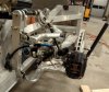
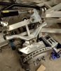
so going with the 930 stubs on the tesla drives. Makes the axels and cv joints easier, and apparently no issue with them handling the torque. everything is ordered, just waiting for it all to come in. Once the new wheel hubs and stub shafts are in I can measure and have 930 CV to axel to 930 CV units made at DSS, basically it is going to have the same setup as most SLC's.

This is the parts list to convert the drives to locked diffs, get single shaft output, and get the the uprights upgraded to the C7 hubs.

2 x gm 23193306 bearing assemblies
2 x DSS 108-GM-O-33 c7 to 930 stubs
2 x zero ev 930-STUB tesla to 930 stubs
2 x zero ev Tesla Drive Unit Driveshaft Outlet Bung Caps
2 x zero ev Replacement Tesla Drive Unit Coolant Fitting 19mm
2 x EV West TESLA-CLIP
2 x EV West MS-GEAR-4.5 gear set reduces drive ratio to 4.5:1 from 9.71:1 (https://www.evwest.com/catalog/prod...d=489&osCsid=02d20ccf4fdff82aa2d617822e02a3bb)

that last part is really expensive, and I am tempted to buy one, and see if I can get a set made cheaper. I will need to have a similar set made for the the front drives, so if anyone knows a transmission or machine shop that cuts there own gears....


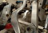
Both open diffs come out and go to get welded. Good video on doing it here.
Was going to by locked diffs, but might as well weld the ones i have first, and if they fail replace them.

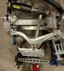
Still need to build custom lubrication systems for the drives. I am basically running them upside down and inclined, so the lubrication pickup points that were at the bottom of the units is now at the top. Was planning to run an external reservoir with electric pump, but need to get the units open to plan it out. I think I can go in and out through the old drain and vent holes with stainless line and direct lubrication right to the needed bearings.

Bob


Bob
 

Randy V

Moderator-Admin
Staff member
Admin
Lifetime Supporter
I’m really curious why the welded / locked differentials....
Have you ever driven anything with locked differentials at speed? I have and I can tell you without a doubt that I will never do it again.
Low speed -
If I lock the differential on the front of my Jeep while climbing boulders, I have to unlock it in order to get the Jeep to turn without pushing / scuffing its way around the turn.
If it is just for Drag racing, I guess I can see it though... I just hope you don’t get out of shape and actually have to drive it!
 

Kyle

Supporter
He’s running two motor units in the rear. So each wheel will have its own motor. My understanding is he just needs to lock the diff in each motor unit separately, that way the other side of the output on the diff just doesn’t spin freely. Without locking the diffs his system doesn’t work.
 
Oh I think you misunderstand the set up. These are two seperate drives, they are not connected to each other. On a stock tesla a single drive with the open diff drives two shafts. On my set up I am driving a single rear wheel with each drive. The diff has to be locked or the shaft will not turn. My setup allows for all sorts of fun like torque vectoring, single wheel burnouts/tire warm up, tank turns, ect. Traction control is achieved within the inverter to the drive, comparing drive rpm to vehicle speeds, and a tone ring.

This setup also allows me to drop the gear ratio, w/O sacrificing low end torque.

Bob
 

Howard Jones

Supporter
Here's my guess. He is using two motors each intended to be used in a Telsa to drive both tires but he is going to drive the left with one motor and the right with the other. wedding up the spider gears ensures that torque will be transferred to the attached stub instead of allowing the spider gears to transfer torque to the unloaded/unused side.

You two guys beat me to the punch. But the remaining question is how will the system differentiate wheel speed in a turn? Or does this matter? I think it does but then I really don't have any experience with this type of electric motor setup. On trains that use one motor per axel, the turns are gradual enough that each wheel speed is controlled by the wheel profile in relation to the track profile. The wheel is cut at an angle so that in a turn the wheel's contact point actually becomes larger in diameter on the outboard wheel and smaller in diameter on the inside wheel.

Are you going to employ some form of anti-spin traction control on each wheel/motor combination? Thsi would reduce torque on the spinning(loss of traction wheel (inside one in a turn). This is an interesting problem and may just be key to actually running this system in a high-performance setting.

The output from a traction control system might be used to control/ modify the power control system's current request/delivery to achieve this. I would be interested in your thoughts on this.
 
Traction control is absolutely necessary with this setup, but not only because the drive are not interconnected. There is going to be a motor on each of the 4 wheels. Even dropping the gear ratio in half, the amount of torque per wheel/pound of car is right up on friction coefficient of the best tires out there, however these get better each year mostly due to EV's pushing the envelope.

On teslas the traction control is via a ABS system kind of like https://racetronics.com/Handling-Control.html or https://3dmmotorsport.com/blogs/mk60-standalone-abs. Basically, wheel slip is detected via abs sensors, and brakes are applied to that wheel to slow it down. As the motorsport guys got their hands on the tesla drives and inverters, and open source control of them became possible, thanks to the work of really a very small group of guys, people are adding electric traction control to the software running the drive inverters. ZeroEV has a inverter code that does it (see a tesla swaped ferrari here with it turned off
) Some system use vehicle speed (GPS) or wheel sensors and modulate drive output every fraction of a second. AEM has come out with a commercial solution, similar to the opensource ones, but with a much more motorsports focus. I am going to be using https://www.aemev.com/products/ev-vehicle-control-units/vcu300 to control the 4 drives. Basically you can tune the torque output for various conditions and driving types, I will probably combined this with a custom 4 wheel racetronics system.

And now for the really crazy idea I had a couple of days ago when I was measuring up the axels, planning the hub conversion, and the swaybar/dual spring rate system for the rear end. The toe adjuster on the rear end is just asking to be replace with an actuator of some sort. There is a youtuber I follow who is building a car with rear steer, and with the electric steering assist I am using, I think I can output steering angle to a CAN controller...and well get rear steer on this thing. Found a rear steer actuator on ebay for 100$ from a TLX, and said lets if it will fit. It came in today, pics of it just layed up on the car for fitment attached. It can't be this easy right? It will need a custom bracket, and a little reaming of boltholes, but I think it will fit, and clear the axels...

Ordering a second one now.

Bob
 

Attachments

  • IMG_20210512_203553.jpg
    IMG_20210512_203553.jpg
    327.1 KB · Views: 309
  • IMG_20210512_203545.jpg
    IMG_20210512_203545.jpg
    258.3 KB · Views: 310
  • IMG_20210512_203612.jpg
    IMG_20210512_203612.jpg
    248.1 KB · Views: 299
  • IMG_20210512_203616.jpg
    IMG_20210512_203616.jpg
    320.5 KB · Views: 316

Howard Jones

Supporter
OK, that's just about what I was thinking. On trains, the propulsion software asks for an acceleration rate that was requested by the driver/ train control system then the traction control (anti-slip) system modifies this. Individual wheel speed is sensed with magnetic speed sensors on each axle and compared axle to axle to prevent dragging a wheel or spinning one on a wet rail etc. This was 50 years ago so I am sure things have progressed.

This is one of the most interesting builds ever to appear on this website. I will be following this one.
 
Thanks howard. its really is pushing the envelope, but thats what i like. The system you describe on the train is almost the exact same here.
 

Randy V

Moderator-Admin
Staff member
Admin
Lifetime Supporter
Okay I get it now and may have somehow missed that in previous posts..
I remain curious about traction control however.
Since the reason for a differential is to allow the wheels on the outside of the turn to turn faster than the wheels on the inside of the turn, how do you plan on accommodating this? My point is - will the traction control see the faster turning wheel on one side vs. the other side as a loss of traction, thereby applying the brake on the faster side?
Whether the axle is physically locked (not applicable in your case) or digitally locked (may be applicable in your case) is moot.
I agree with the others. You have a fascinating project!
 

Randy V

Moderator-Admin
Staff member
Admin
Lifetime Supporter
Okay - time shift got me... I just read your other responses. I think I have it now...
 

Howard Jones

Supporter
I can see that this is a very unique situation. Normally the problem is a single torque source driving two wheels and accounting for the torque split that allows the two wheels to turn at different speeds. We use a differential and all is well. Here however we have two torque sources independently driving their own wheel and being requested to turn them with the same torque, single throttle position request, and then account for differential wheel speed when the car is in a turn.

I think what is needed is independent wheel speed sensing and then a control system that can reduce torque request on the motor that is on the slower turning wheel. Maybe even sense traction limits as well as speed on each axle and control/modify all four motors continuously and independently.

I have been looking at some industrial controls sources a bit but I have not found an application like this anywhere. Clearly, in the automotive industry, they are all using a version of traditional one motor on each axle and a differential of differing technology to account for varying wheel speeds and traction limits.

This thread will get really interesting (more than it is already is if that's possible) once you get the car to the go-cart phase. At this point, I would only advise that you plan for individual wheel speed sensors and their mounting.
 
Last edited:

Neil

Supporter
Howard, A PM DC motor has perfect characteristics for this application- drive the motor with constant current and you get constant torque.
 
What you describe, is exactly how the system operates. Each motor has it own sensor, and adjusts output to match. You can do really interesting stuff when you link it to a 3axis sensor. You can apply more torque to out side where to vector through turns. You can drive the left side forward and the right in reverse to do tank turns....it gets nutty. I built a rc car with 4 brushless motors to test the vehicle dynamics prior to the full scale build, and its just incredible what you can do once you start digitally controlling each wheel.
 

Scott

Lifetime Supporter
I have been looking at some industrial controls sources a bit but I have not found an application like this anywhere.

Howard, dual independent electrical drives might seem new to automotive, but it's common elsewhere. Many years ago some code to implement differential steering for tank treads driven by two independent electric motors. I developed the PID module from scratch... If you aren't familiar with proportional–integral–derivative (PID) controllers they're really important type of control loop to control these types of systems (PID_controller). Just like your brake bias, it takes time to tune them. Rather than turning a physical knob your tweaking coefficients.

This dual independent drive design pattern is commonly seen with three-wheel robots where the two rear wheels are independently driven to steer the robot.

I subsequently tried writing some code for a quadcopter from scratch in the early days. In that case you're driving four independent motors to hover, fly, bank, flip, roll, etc. Rather than monitoring wheel speeds you're looking at accelerometers, but a lot of the concepts transfer. That project didn't end well. -- like never got it to even hover well if there was a breeze These days there are all types off-the-shelf controllers which makes things much easier to implement. The new AI-based systems are scary at how fast they improve flying.
 
Last edited:

Neil

Supporter
Build your PID controller with analog circuits and you will be, literally, tuning it with physical knobs.
 
Hubs, rotors, calipers and one set of stub shafts are in. Waiting on the C7 stub shafts from the drive shaft shop. Sketched up my rear adaptor, it is attached below. I am going to retain the stock SLC off set, and use my ccw 18 inch rims for now, maybe go to the forgeline 20/19's at some point. It looks like the z06 carbon ceramic rotors will fit the 18's

Still need to draw up the caliper mount, and probably mount a tesla parking brake while I am at it. have to wait till the rotor is on to do that.

Also have my suspension modifications for the rear finalized. Will show drawings soon.
 

Attachments

  • hub spacer 45.625 cetner hole.jpg
    hub spacer 45.625 cetner hole.jpg
    80.9 KB · Views: 254
Bob:
Fantastic work!! I tried to go the electric route before I restarted my build but it turned out to be very difficult to get rid of all the parts I had purchased already, the crate engine, transmission, fuel system and so on, Jegs would not take the crate engine back and Fran was not interested in taking back all the parts including transmission. It would have been fun to follow your lead. Keep up the good work, very exciting project and you are doing a superb job. Thanks for sharing your progress.
 
Thanks Hector I often think I bit off more than I can chew with this one, but I really am in no hurry to get it done. Picked up a nice fun car to drive for the summer, and having a lot of fun and learning a whole lot, so it is a big win for me.

I spent a good year and a half looking for a unfinished project to buy. Lost out on 2 ebay auctions (mostly due to my falling asleep at the wheel, both of which are now good build logs here), passed over 2 private sales, and lost a copart auction to a questionable computer "glitch" (got real lucky on that one) before I found exactly what I was looking for. Clean car, almost unfinished, no motor or trans. I still am upgrading almost everything, but having all the original pieces in had, really helps with the design process.

I am waiting for adaptors and brackets to come in from CNC, and a couple more rear suspension parts, but very soon I think I will have the rear end mechanical done. Should be real interesting, nothing like it done on a SLC, or really any home built car I have seen before.

I also just picked up a really nice handheld 3d scanner, its Artech, for a song. I am going to rescan my front end before I send the front end off to laser cutting. Learned my lesson doing the rear. Highly accurate scan is a must. I wasted so much time doing revision in MDF, working to the one and done process now.

Bob
 
Back
Top