Brake rotor hat measurement parameters.

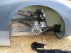
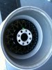
Hello forum members. I am on the next step in my build which is having brake rotor hats and caliper brackets made for my car. I have my wheels and their measurements. I have the uprights, their mounting ears and the hubs contained within them and their associated measurements. I also have the brake rotors. The issue I'm having is that the dimensions the fabricator is asking for I cannot give based on what I have here physically. In order to make the rotor hats, he needs proper offset numbers but to give him proper offset numbers I need the measurements for backspacing of the calipers which is based on the brackets, which I don't have either.

So my question is this: should I come up with an arbitrary number for one so it will dictate the measurement of the other, or is the offset of the brake rotor based on particular parameters? What is the proper way to judge how the caliper and rotor fits inside the wheel axially? I am trying to measure two items that are in space and I don't know where to start. Thanks in advance.
 
Joe,
You will have to fabricate a caliper mounting bracket first. For mock-up you could use 1/4 inch plywood or particle board. Make a cardboard template first that gets the caliper the right distance away from the hub/upright and located so that the pads will ride on the rotor when you install it. (just make a cardboard template too for the rotor) Once you have the caliper bracket made and mounted, then you can take measurments for the rotor hats to be built. Sorry I don't have pics, but there are lots on here of scratch-built cars.
Best, Scott
 

Tim Kay

Lifetime Supporter
Joe, obviously it's always better to have all the parts. But if you're truly going to attempt it with limited necessary items then it's possible to "backwards engineer" with some certainty. You're still gonna need some key measurement. I'm not quite clear on what parts you physically have or if your doing front and/or rear but as long as you have full dimensions at hand of rotors and calipers, you can proceed.

Let's start with the rear setup first. With upright, stub axle, bearing carrier, wheel adapter and wheel in a mock up assembly (basically everything assembled short of caliper, rotor & hat) you can then measure to get the caliper to the necessary clearance away from the inside of the wheel. This measurement will now allow you to locate the mounting position of the caliper to the upright (whether directly on the rear or with a caliper mounting plate on the front). Now you can locate the rotor and get the correct hat dimension from there. I'm simplifying it here but it can be done. I think the main concern to start with is inside clearance of caliper to wheel.

Again, I don't know if you have calipers yet and are they radial or lug mount? I had great luck using Wilwoods schematics in their online catalogs. If I may suggest, Fran (RCR) was my best source for Wilwood brake kits. Also, don't forget about your parking brake.

Tim
 
Joe:

I would go with rotors that are off the shelf pieces. Generally a 12.19 or 11.75 O.D 1.25 or.810 thick on a 8 bolt x 7" bolt circle are readily avialable AP Racing, Coleman Racing products or Wilwood carry these types of discs. Hats are readily available for them in many offsets.
 

Seymour Snerd

Lifetime Supporter
should I come up with an arbitrary number for one so it will dictate the measurement of the other, or is the offset of the brake rotor based on particular parameters? What is the proper way to judge how the caliper and rotor fits inside the wheel axially? I am trying to measure two items that are in space and I don't know where to start. Thanks in advance.


I think the essential question Joe is asking may have been missed so far, but please correct me if I'm wrong. I think what he is asking is, given the freedom to place the rotor center plane anywhere within a range of lateral positions, how does he choose where to put it? For example, he could push it all the way outward until it barely clears the rotating wheels. He could push it all the way inward until it hits the end of a suspension arm or part of the upright. Or he could put it anywhere in between. The issues that come into play that I can think of right away are:
  1. What position provides the best rotor and caliper cooling?
  2. What position allows the simplest, stiffest, strongest, lightest cheapest caliper bracket?
  3. What position is best in distributing loads to the wheel bearings?
  4. What position minimizes hat cost and mass and maximizes hat stiffness and strength?
  5. What position provides the least unsprung weight?
  6. What position provides the least rotational inertia?
My essentially worthless intuition is that placing the rotor and caliper as far inward as possible improves cooling, bracket stiffness and simplicity (although it depends on the shape of the upright and lugs), but increases hat depth which increases hat mass and cost.

I wonder if any of the race car design texts address this issue.

Without that, if this were my problem, I would probably focus on item 2 given the nearest standard hat size (as Dave suggests), but that's basically because I don't know how to evaluate all the others with any useful precision.

The only other thing I can think of to do is look at some existing successful designs from this point of view and try to see if there was one rule that dominated, like "as far inward as possible" or "caliper bracket short and sweet".

(BTW, Joe has rotors, so radial position is set).
 
Last edited:
Many thanks for your thoughtful replies. You have helped me go in the proper direction with your considerations.
Dave, good memory, and yes you have helped by sending me the measurement data sheets and putting me in touch with a fabricator.

I had some thought about what it is that I'm trying to accomplish and really, the largest consideration first and foremost is the caliper not hitting the inside of the center section or the inside radius of my rim, meaning that the rotor hat offset will be the starting dimension, and once that has been established it will dictate the position of the calipers and hence the caliper brackets. I'm going to map this out on paper carefully because I only want to do this once. I don't have much room to play with radially (rotors are 328mm/12.9in) but I have a ton of room axially, with the front rims being a total of 11" wide and the rears 17".

For anyone undertaking this same thing in the future, I have included a photo of the zone of the rim that I think is the spot where I think the measurements should spring from. There are a few radii there between the magnesium webbed part (black area in the crummy photo) and the area where it meets the aluminum rim that I will have to account for in making sure the caliper doesn't rub on the rim. I have also included two data sheets showing measurements of rotors and hats that are all considerations in having these components fabricated. I am not associated with the vendor, but a big shout out for his patience with me... Apparently these documents are available on the Wilwood site, but they either wouldn't open for me or I couldn't find them. Can't remember, my mind is spinning with brake stuff and numbers and notes and internet...

I think I will take aladinsane's advice and work on a mockup to hold this stuff in place in the rim whilst I work the vernier calipers...
 

Attachments

  • IMG_0249.jpg
    IMG_0249.jpg
    123.9 KB · Views: 373
  • 119-09.pdf
    107.2 KB · Views: 807
  • 116-09.pdf
    385.6 KB · Views: 423

Howard Jones

Supporter
One last idea. As you locate the caliper in mock up, take into account the off the shelf hats avaiable from Wilwood. Once you have a aprox. location for the caliper choose a hat from Wilwood that gets you as close as possible. Then alter your custom caliper mount to suit.

Not only will you be able to use standard stock hats should you need to replace one later but unless you can turn one up on a lathe youself , you can get them much cheaper and sooner.

Wilwood also makes undrilled hats. The undrilled ones actually add a couple of offsets widths to the selection of drilled ones. Between them you should be able to find something that will work for you without custom made hats.

If given a choice I would locate the mass of the brake system as close to the centerline of the car as possible and as low as possible. In the end you will find that the caliper location will dictate most of the rest of the variables.

One more lastly........ check and check again interference between the rotor and the lower A Arm in droop. Be sure you have located the rotors far enough away from the ball joint end of the a-arm so as not to make contact in full droop, both ends of the car, and full steering angle at the front.
 
Last edited:
Sound advice Howard all the way around. I saw limited offerings at Wilwood as far as 4-bolt hats, I didn't think about un-drilled ones. As far as having the rotors/calipers as far inboard as possible I'm in total agreement for several reasons and I will do an interference check as you suggest. Cheers!
 
Unfortunatley most of you have missed an essential part of the whole debate, Howard got closest by mentioning the steering arm, but one of the most important locations to determine in your front suspension/hub/brakes area is the exact position of the steering knuckle joint, if this is wrong, ackermann wont work and the car will steer like a whale. In most designs where the steering rack is in front of the axle line, the position of the steering knuckle is well out from the centre line of the car, sufficiently to affect the position of the brake disc, which then positions the caliper, wheel etc etc. Ignore this and you are doomed to a car that wont like going round corners. Take for instance, the standard "English" Ford Granada derived upright with cast in steering arm, used on many GT40 replicas, to get the Ackermann anywhere near right on this set up means that the steering joint needs to be moved nearly 40mm outward towards the wheel to get the scrub radius anywhere near right, this puts the joint into conflict with the disc, so the disc has to move, the caliper has to move, etc etc. Designers start by locating the steering joint, then hang everything round that. Think about it !
 

Seymour Snerd

Lifetime Supporter
Unfortunatley most of you have missed an essential part of the whole debate, Howard got closest by mentioning the steering arm, but one of the most important locations to determine in your front suspension/hub/brakes area is the exact position of the steering knuckle joint.... Think about it !

Excuse me Frank, but I think you're the one that needs to do a little more thinking (or reading). This thread has nothing whatsoever to do with suspension. This is about positioning the caliper and rotor within an existing suspension system.

You could start out by looking at the thread title, then read the first post.
 
OK , my mistake, but still an important element to consider, seems like the guy is still at an early stage of build rather than modifying an existing car. My apologies
 
You know, I feel I must clarify some things which I may not have gotten across properly at first. I think this thread has become confusing.

The car is a roller.

It is not a GT40, it is a McLaren M1C copy.

I have everything needed to complete the brake system except:
1. Disc rotor hats
2. Radial brake mounting brackets

The general gist of my first post was that these two items above need to be fabricated custom as they are not available off the shelf. In order for proper measurement to be made for one, the other needs to be in place which is a classic paradox, hence my reaching out to the membership here. I am now well on my way thanks to you all.

Here are photos, because well, everyone loves photos and maybe it will put this thread back in it's proper context. These are the bits I am measuring in order to get everything to fit properly. Thanks again to you contributors. Hope that somewhat clarifies things.
 

Attachments

  • frontupright.jpg
    frontupright.jpg
    286.9 KB · Views: 422
  • discinrotorwithpadscentered.jpg
    discinrotorwithpadscentered.jpg
    178.8 KB · Views: 486
  • insiderim.jpg
    insiderim.jpg
    134 KB · Views: 362
Last edited:
If you look at almost any front brake setup, you'll see that the rotor is positioned as close to the lower ball joint (or the steering arm*) as possible. That's to get the rotor as un-shrouded by the wheel as possible for cooling, plus allow enough clearance for the caliper. The latter is especially important when you use non-floating calipers, which tend to take up more space toward the outside.

*You don't necessarily have to move the upright arm toward the outside to increase Ackermann. You can alternately shift the rack centerline closer to the upright axis lateral position. However, positive Ackermann isn't even used on race cars. It works against the high slip angles of high cornering speeds. So the ERA is a compromise, having about 50% Ackermann compensation built in. You'll only notice tire scrub when parking.
 

Howard Jones

Supporter
Looking at your pictures, I think that I would attempt to locate (mock up wood hat, stacked washers etc.) the brake rotor as near as possible to the end of the wishbones as I could and maintain good clearence. 1/8 to 1/4" is plenty as long as this is a min through full travel. Again look at the standard Wilwood hat drawings for a starting point. Then I would make my radial standoff (caliper adapter).

Pictures are always a plus. Frank... good stuff on the front of GTD's with Granada upright. Someday we should all have a long dicussion on how to fix the suspension on GTD's. Maybe we can set a record on thread reply count! I love betty (my GTD) but she gets better every time I replace a part. Good cars......as long as you replace all the parts!!!!!
 
Please find attached a disc bell drawing for a 11.25" rotor, Wilwood part number 160-3846.

This disc bell is for a Granada hub, but it might help you get something down on paper that you can then modify.

This kit uses the Wilwood narrow Superlite 6 pot caliper.

If you look on the Wilwood website they give you caliper drawing and mounting details.

It's easy if you can draw it up on CAD as you can move things around.

If you need any further help, and can take some measurements etc, then PM me and i'll see if i can knock something up for you.

D.
 

Attachments

  • BK5E-Bell.pdf
    17.3 KB · Views: 402
I did a mock up today with the caliper in the front wheel and it looks like the sway bar rod that links the lower wishbone to the actual sway bar will be the only thing that hinders any type of motion (and that's a "maybe"). However, with a simple z bend I think that can actually be alleviated. The sway bars will have to be constructed as well, so I'll just configure them accordingly. Otherwise, steering seems to be unaffected.

Thanks for the pdf, gtstuning, it will help. Part of my issue is my lug nut pattern is 4 bolts, in a 108mm pattern. If it weren't for that, I could virtually just pick and choose hats off of the internet till I happen on the right thing, they are that cheap. Today I saw a used Brembo piece on ebay for $9.95 buy it now price.

I did find the un-drilled Wilwood rotor hats and it is a very viable option once I suss out the width dimensions (85 bucks a pop, not bad). AP provides schematics with brilliant detail. You know, if I'd followed in my dad's footsteps and become a mechanical engineer, I could probably figure this all out on paper and wouldn't have to bother you all, but this is the fun part of a build...

I've stopped mucking about with the dash and am starting to devote all my attention to the brakes which will probably be the biggest technical challenge of the build.
 

Attachments

  • cp5850-1cd.pdf
    210.2 KB · Views: 351
  • cp3870-120~1cd.pdf
    121.8 KB · Views: 294
Last edited:
Back
Top