Cadillac Alternator Jumper Wire? - Need Electrical Insight

I'm using the 2004-2007 Cadillac alternator 150AMP (GM 84009383). I'm having an issue (electrical is not my strength), but the volt meter in the cockpit will at time show a strong 14 volts then fall to about 12.5 volts and then migrate back up to about 13.5 or so (as best I can read the volt meter). I see this alternator is self governing (turns on via RPM??), and via diodes and rectifiers controls output thru signals from the ECU (I think).

In looking at the internet I see a jumper wire from the output stud on the alternator (same stud going to battery) back to the pins that the GM single wire harness plug connects.

Should there be a jumper wire on this unit?

Thanks
 
Dan,

the modern GM one wire alternators require a voltage feed to “excite” them. These are the ones with a four pin connector on the back side of them. You need to connect the exciter wire to a switched 12 volt connection. If you have a 2 pin connector on your alternator it is ECU controlled, way more complicated to deal with unless you have the proper GM ECU.
 
Dan,

just looked up the PN of the alternator you have and it is a four pin. Summit and others sell a plug to connect this. In addition to the plug and wire there is a resistor that is required in the circuit. One option is Painless part number 30705. Holley also makes one, PN 197-400 (I think that is the one I used).
 

Johan

Supporter
Dan, if it’s a 4-pin , it should be marked P, L, I, S.
P= rpm, not used. L=control lamp or resistor. I= ignition +12V (exiter). S= sense, connect to bus bar where you pull a lot of current or to battery.( for the internal regulator to get a more accurate demand info.)
The alternator should work fine without the S-terminal connected.

If it’s a 2-pin, they are PWM from the ecu on the L-terminal.
 
Here are my test results:
1. Alternator is actually a two pin. I did not take the loom apart, but the single wire from the 4 pin connector is on the on the I or L (cant get a good angle to read it clearly) pin of the alternator. What I don't recall and didn't record is the source of that wire from the car/engine harness, aka is it from the GM engine harness that came with the LS3/480 GM kit or did I add it (yes I should know, but cant find it in my notes) I will have to check for a resistor that Kurt's two finds reference (#3) as an inline resistor (I noted single wire on the Holly version - like mine).

2. Next I connected an external volt meter to the battery and checked the following:
a. All power off the battery read 12.86v
b. Started engine - external voltmeter read 14.10v -14.22v. Cockpit voltmeter 13.8v
c. Turned on the AC. That activates the two radiator fans, cockpit blower and AC compressor. External volts read 13.87v and cockpit volts 13.0v

Someone can correct me, but I think my system is operating as it should.

What does any one else think?

Thanks
 

Johan

Supporter
Dan, check out my post #207-209, there’s a link to the Corvette forum that explains how the 2-pin works.
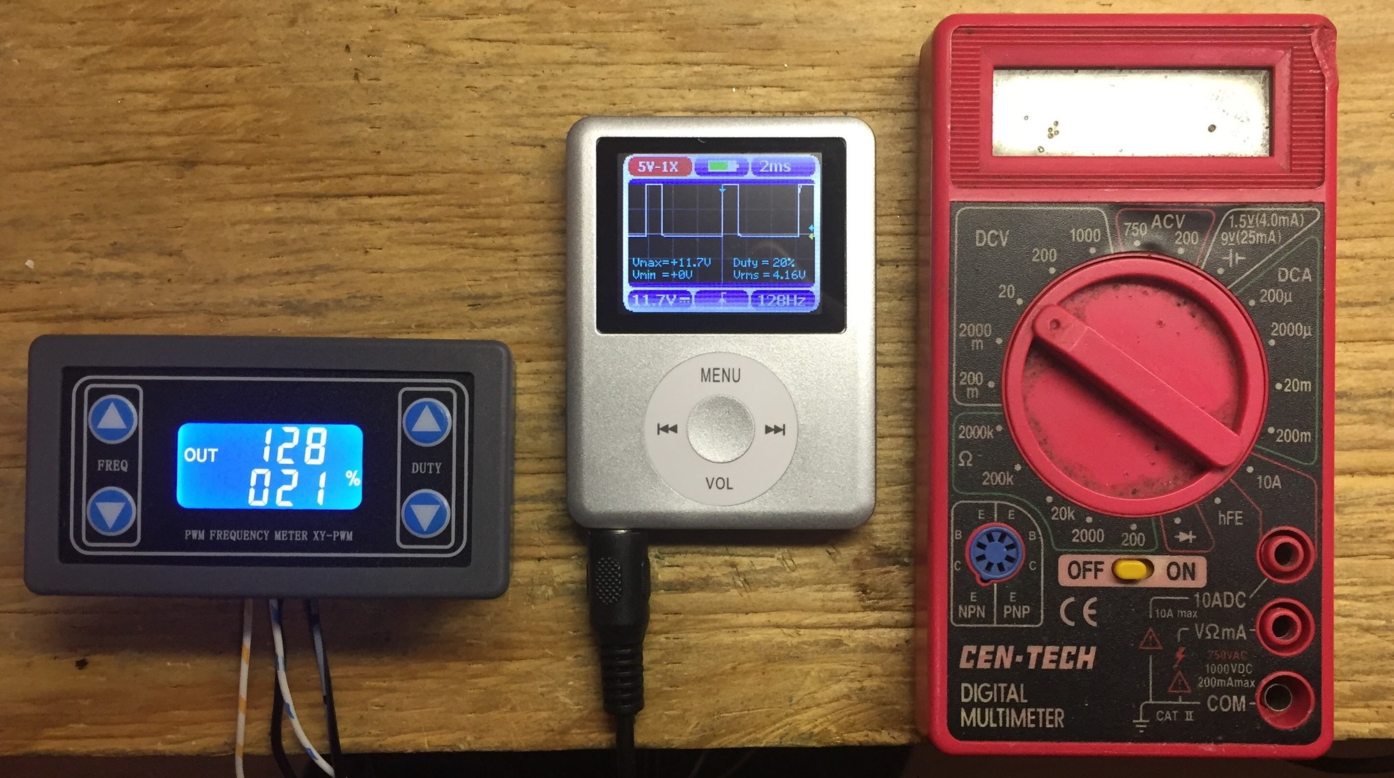
If no PWM signal to the L-pin the alternator will go into default mode, approx 13,6Volts, most likely not enough for our needs.
 
13.87 volts at the battery under full system load is good, alternator appears to be operating fine.

I had done a lot of research on the two wire alternator because that is what was on my donor engine. I am running a Holley ECU so I have no alternator control. I switched to a four wire alternator for my build.

I think the issue with a two wire not connected to the ECU is either it will not charge properly at low RPM or it may overcharge the battery. I’d have to read up on it again to say for certain.
 
Johna/Kurt good input. I'm going to call GM Performance and find out what type signal is coming from their harness (I think its their pre-wire in the harness). Hopefully they did all the resistor and what not to make the connection a plug and play.
 
Thanks. I took a look at it. What I'm not certain about without stripping the wire looms, is if GM built in the resistors into the harness and if it requires a jumper line as shown on numerous diagrams. I sent these questions to GM. Waiting to see what they say.

Thanks
 
OK folks the word from GM: FYI

Configuration - engine harness 19166573 and ECU 19258267 for a LS3/480 and are using alternator 84009383 (Cadillac CTS V, 2 pin with 4 pin connector slot). Instruction sheet 19171935 does not address connecting the alternator.

Asked GM to confirm:
  1. The single harness wire (with four pin alternator connector) is a plug and play for this alternator (aka alternator does not need a jumper from alternator stud to vacant alternator pin or resistor).
  2. What excites the alternator?
GM response: Harness is plug and play. ECU excites the alternator to supply the charge.
 

Steven Lobel

Supporter
OK folks the word from GM: FYI

Configuration - engine harness 19166573 and ECU 19258267 for a LS3/480 and are using alternator 84009383 (Cadillac CTS V, 2 pin with 4 pin connector slot). Instruction sheet 19171935 does not address connecting the alternator.

Asked GM to confirm:
  1. The single harness wire (with four pin alternator connector) is a plug and play for this alternator (aka alternator does not need a jumper from alternator stud to vacant alternator pin or resistor).
  2. What excites the alternator?
GM response: Harness is plug and play. ECU excites the alternator to supply the charge.

I have this setup (I believe).
I have a remote battery disconnect/kill switch.
It kills all power, but engine continues running after I hit the button.
I need to (I think) cut the wire and run it separate to the kill switch to fix it.
 

Ken Roberts

Supporter
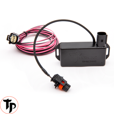
Tick Performance now has a solution to the problem if the ECM doesn't provide a signal to the 2 pin alternator.

 
Back
Top