The fan's free air (stand alone) ratings are meaningless numbers that look good for advertising. Any pump or fan (a fan is an air pump) reduces flow as the back pressure increases. Industrial fans have a flow vs pressure graph in their data sheets. Your measurements provide a valuable data point for comparing fan performance.

- Forums
- GT40 Replica Manufacturers' Corner
- RCR Forum - RCR40/SLC/917/Superlite Aero
- The SLC Clubhouse
You are using an out of date browser. It may not display this or other websites correctly.
You should upgrade or use an alternative browser.
You should upgrade or use an alternative browser.
Kurt H (hoffkm) SL-C build thread
- Thread starter Hoffkm12
- Start date
Thanks!Mark,
I purchased my rear tow eyes from McMaster Carr. They are female threaded lifting eyes that I painted red. They are only available in course threads so I had to change out the pivot fasteners. And yes, tie down points for trailering are what I “plan” to use them for, hopefully nothing else.
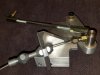
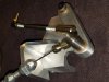
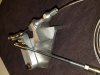
Had a request for my throttle pedal cable linkage design so posting it up here for all to share. There is a design for a 3D printed version and one machined from aluminum. All the required bronze bushings, fasteners, cable, etc. are spec'ed out on the BOM of the assembly prints for each version.
Attachments
Thank you Kurt,Had a request for my throttle pedal cable linkage design so posting it up here for all to share. There is a design for a 3D printed version and one machined from aluminum. All the required bronze bushings, fasteners, cable, etc. are spec'ed out on the BOM of the assembly prints for each version.
This is the last piece I need to finish my throttle assembly.
Once again life has gotten "in the way" of progress on the SLC. Trying to commit one night a week to working on it again soon.
In the meantime, my brother and I built a paint booth in my shop using professional quality fans (11,000 CFM total) and paint booth filters so that I can paint his son's truck. Took a couple of days off work to get it painted. Finished the jambs, back of cab, and front of bed this morning. Paint booth works exceptionally well. When it comes time to paint the SLC I will be ready.
Filter box with two 5,500 CFM TEFC motor fans

divider wall with intake filters folds up to ceiling when not in use


The airlfow is perfect, filtration is good (sucks the overspray out right away, even the clearcoat, but does not blow it outside), but I do need to add some additional lighting before I paint the SLC. I can see but not as well as I would like.
In the meantime, my brother and I built a paint booth in my shop using professional quality fans (11,000 CFM total) and paint booth filters so that I can paint his son's truck. Took a couple of days off work to get it painted. Finished the jambs, back of cab, and front of bed this morning. Paint booth works exceptionally well. When it comes time to paint the SLC I will be ready.
Filter box with two 5,500 CFM TEFC motor fans
divider wall with intake filters folds up to ceiling when not in use
The airlfow is perfect, filtration is good (sucks the overspray out right away, even the clearcoat, but does not blow it outside), but I do need to add some additional lighting before I paint the SLC. I can see but not as well as I would like.
That was a nice add onMark,
I purchased my rear tow eyes from McMaster Carr. They are female threaded lifting eyes that I painted red. They are only available in course threads so I had to change out the pivot fasteners. And yes, tie down points for trailering are what I “plan” to use them for, hopefully nothing else.
Thank you Kurt,Had a request for my throttle pedal cable linkage design so posting it up here for all to share. There is a design for a 3D printed version and one machined from aluminum. All the required bronze bushings, fasteners, cable, etc. are spec'ed out on the BOM of the assembly prints for each version.
I machined the linkage today from 6061-T6 and it turned out really nice.
Attachments
Thank you Kurt,
I machined the linkage today from 6061-T6 and it turned out really nice.
Stephan,
Glad the design worked out for you. The pieces turned out beautiful, excellent work on your part! Where did you get your throttle cable? I like the termination on yours better than what I did for mine.
Hello Kurt,Stephan,
Glad the design worked out for you. The pieces turned out beautiful, excellent work on your part! Where did you get your throttle cable? I like the termination on yours better than what I did for mine.
Here is the part number for the throttle cable.
Part # 491TC1000HT96
Lokar TC-1000HT96 Hi-Tech Throttle Cable Kit, 96 Inch, Stainless
Update:
I have finally been finding regular time each week on Wednesday night while the darling wife is teaching religious education at Church to work on the SLC.
I recently finished my nephews truck. As is usually the case, more tasks were added and we sprayed in a bedliner.


it is not perfect but it is good enough for a 16 year old and looks 1000 times better than it did.
Progress on the SLC:
1) Began laying out the design of my front clam hinge
2) Added reinforcements to the rear hinge
3) Bonded re-inforcement plates to the front and rear clams
4) Install the front radiator air deflector
5) Sprayed SEM Pro-Tex on the underside of the rear clam (I do not recommend this product. I have used the PPG equivalent which is very touch and durable but the SEM product is basically nothing more than thick paint). I will be applying bed liner over this for additional protection.
6) Mounted the interior door cards on the doors (mine fit very nicely, I know others have had issues, guess I got lucky)
7) Cut out the lip on the front and rear wheel wells for tire clearance
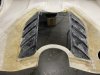
8) Cut out the air intakes on the top of the rear clam (this was a nerve racking experience)
9) Mounted the doors on the hinges and have everything gapped, lined up, and functioning
10) Designed 3D printed tail light buckets that I will bond into the rear tail light covers for my Lotus Elise tail lights (more to come on that)
11) Finished the design of my door actuator system utilizing Progressive Automation actuators. I will be fabricating the brackets and installing these over Christmas break from work.


I have finally been finding regular time each week on Wednesday night while the darling wife is teaching religious education at Church to work on the SLC.
I recently finished my nephews truck. As is usually the case, more tasks were added and we sprayed in a bedliner.
it is not perfect but it is good enough for a 16 year old and looks 1000 times better than it did.
Progress on the SLC:
1) Began laying out the design of my front clam hinge
2) Added reinforcements to the rear hinge
3) Bonded re-inforcement plates to the front and rear clams
4) Install the front radiator air deflector
5) Sprayed SEM Pro-Tex on the underside of the rear clam (I do not recommend this product. I have used the PPG equivalent which is very touch and durable but the SEM product is basically nothing more than thick paint). I will be applying bed liner over this for additional protection.
6) Mounted the interior door cards on the doors (mine fit very nicely, I know others have had issues, guess I got lucky)
7) Cut out the lip on the front and rear wheel wells for tire clearance
8) Cut out the air intakes on the top of the rear clam (this was a nerve racking experience)
9) Mounted the doors on the hinges and have everything gapped, lined up, and functioning
10) Designed 3D printed tail light buckets that I will bond into the rear tail light covers for my Lotus Elise tail lights (more to come on that)
11) Finished the design of my door actuator system utilizing Progressive Automation actuators. I will be fabricating the brackets and installing these over Christmas break from work.
Attachments
Has anyone else noticed that the gap between the driver side door and the rear clam is not consistent at the top? I have a very consistent gap from the bottom until you get up to the point where the door and clam curve to horizontal at the roof then it opens up about 3/16". I can easily fix this with fiberglass, just curious if anyone else has experienced this. You can see it in the picture above, sort of. Still more gap work to do but they are close enough that I know I can get them all where I want them at final fitment.
")
Since I have the doors installed the next step was to actuate them. Credit for my electric door design goes to Allan for his original design and to Mesa for his mods for the gas strut design on his doors. I basically replaced the gas struts in Mesa's design with electrical actuators from Progressive Automation.

I laid this out in CAD to design my brackets and verify things would/should work as planned.


I had to first modify the actuators to install spherical rod ends on them to accommodate the motion of the doors on their hinges. This is not a simple motion like a typical door hinge that rotates thru one plane.
I fabricated brackets to mount into the doors to attach the actuators, install a bracket on the spider from Progressive Automation, and cut out the doors for what CAD showed me I needed for clearance.


Everything worked as planned. A video is below of my initial testing. The loud scraping noise is the cylinder rod rubbing on the opening in the door, I need to add some more clearance but I forgot to open the valve on my air compressor that feeds my shop when I went out there last night and was not walking all the way back in the cold and snow. I'll correct that when I get back out to my shop to install the passenger side and wire up the relays and remote to make this package complete.
I laid this out in CAD to design my brackets and verify things would/should work as planned.
I had to first modify the actuators to install spherical rod ends on them to accommodate the motion of the doors on their hinges. This is not a simple motion like a typical door hinge that rotates thru one plane.
I fabricated brackets to mount into the doors to attach the actuators, install a bracket on the spider from Progressive Automation, and cut out the doors for what CAD showed me I needed for clearance.
Everything worked as planned. A video is below of my initial testing. The loud scraping noise is the cylinder rod rubbing on the opening in the door, I need to add some more clearance but I forgot to open the valve on my air compressor that feeds my shop when I went out there last night and was not walking all the way back in the cold and snow. I'll correct that when I get back out to my shop to install the passenger side and wire up the relays and remote to make this package complete.
Jeff,Can the actuators be backdriven to allow for manual opening?
No, you cannot backdrive these actuators. The utilize an ACME screw which cannot be backdriven (square shaped threads) as well as there is a worm gear on the motor driving the screw which will also prevents them from being backdriven (to a degree). This "holding force" of the actuator is what holds the door open and closed. The nice aspect of these actuators is they have internal switches at the end of travel that stop the actuator when it reaches it's end of stroke, greatly simplifying the electric circuit.
For emergency exit in event of a failure I have the lower pivot point held with a quick release pin like others have done before me. I also plan to screw my side windows in instead of bonding them in place. If I am locked out I can remove the window and pull the pin.
I am also placing a manual override switch in a hidden location that bypasses the relays for the dash switches and remotes in case of an electrical failure.
Thanks for the reply. I was looking at units with the capability of backdrive, but like you said it makes for more "switchology". I'm hoping avoid the need for a release pin and a way to re-set it in event of electrical issues. Not trying to takeover the thread, but has anyone successfully used a backdrive-capable linear actuator with gas pistons?
Similar threads
- Replies
- 12
- Views
- 884