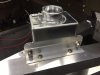
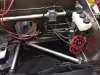
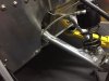
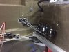
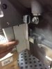
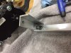
With the firewall not being available for mounting, and the body overhang on the GT-R being rather significant in going past the firewall, I wanted the coolant header tank to be mounted as high as possible and to be accessible. The lateral frame rail seemed to be an obvious mounting location. I added an "L" bracket to allow me to get the mounting as high as possible. It looks a little lonesome there by itself, but I will be making some additions to this area to give it a more finished look. Also, the mounting brackets need to be finished off with steel wool and protectant.

- Forums
- GT40 Replica Manufacturers' Corner
- RCR Forum - RCR40/SLC/917/Superlite Aero
- The SLC Clubhouse
You are using an out of date browser. It may not display this or other websites correctly.
You should upgrade or use an alternative browser.
You should upgrade or use an alternative browser.
Mark's GT-R Build
- Thread starter mksetter
- Start date
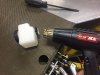
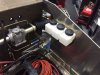
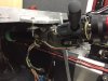
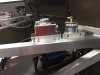
With the front end mounted, I can start filling it up. One of the first things that I did when I got the car was to mount the Wilwood brake reservoirs. It ends up that I wish I had not done that because I decided to use AN fixtures and braided lines to connect the to the Tilton pedal system. If I had not drilled and mounted the reservoirs, I would have switched to the Tilton Reservoir, since it has AN fitting attachments. Having the Wilwood's mounted, I did not want holes, so I went ahead and finished the Wilwood reservoirs, but had to use AN to hose connections to make it work. Less than ideal, but it will work.
I have read that one way to reduce the risk of the Wilwood reservoirs leaking is to use a heat gun on the base of the tank before mounting them, so I did follow that suggestion.
I have read that one way to reduce the risk of the Wilwood reservoirs leaking is to use a heat gun on the base of the tank before mounting them, so I did follow that suggestion.
Attachments
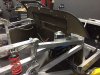
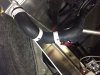
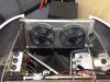
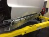
I followed Dean's method of installing the coolant tubes by cutting up two Gates pre-molded radiator hoses. I have yet to stabilize them with mounting brackets, but it was rather easy having the 1.5 inch stainless tubes from Superlite.
Attachments

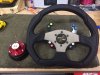
I am using the Summit Raptor Pro wireless steering wheel mounted switch system, so I will not need the stalk mounted GM switches that came with the car. I still want the tilt steering column, so I left that feature intact. I will need to figure out the trim needed to cover the column, but that is for another day.
Attachments
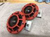
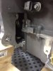
The Hella horns state that you can not modify their mounting brackets in any way or it will change the sound and void the warranty. With that in mind, I made two small mounting brackets to get them in place. One thing I had to keep in mind while mounting these and the lift system reservoir is the space the "nostrils" in the hood take up in the front area. The coolant tubes needed to be kept to the side and low as well because of this concern.
Attachments
Thanks for following the build Fernando. I know I bounce around more than some others might do, but I work on multiple things at a time.
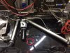
Today I mounted the battery box and installed the suspension lift system. I mounted the hydraulic pump on rubber washers to reduce the vibration noise. I also did this with the shifter and the fuel pumps previously. I decided to use the center position for ease of installation and adjustment of the relief valves, and also to get some weight on the passenger side of the car, since I will be the only one in the car much of the time.
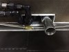
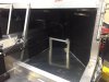
For the longer braided line running on the driver side, I put an "S" in the line and attached one point to the floor of the radiator box. This should allow for movement of the ram cylinder without stress on the fittings. The passenger side is a shorter run, so it did not need that same arrangement.
For the longer braided line running on the driver side, I put an "S" in the line and attached one point to the floor of the radiator box. This should allow for movement of the ram cylinder without stress on the fittings. The passenger side is a shorter run, so it did not need that same arrangement.
Attachments
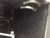
Most of the GT-R builders that I have seen are able to put the coolant lines and the heater hoses in the tunnel under the gas tank, along with the brake lines, fuel lines and some wiring. I made an error that will not allow me to do the same thing. I used -8 AN fuel line and wanted the fuel lines to make the angle towards the fuel pump immediately after exiting the tunnel. Both of these were probably a mistake. First of all, -6AN is large enough line for the 600 hp I will be running. Secondly, if I were to do it again, I would make sure the fuel lines are completely out of the tunnel before beginning the AN fittings. They take up too much space.
To compensate, I am running heater hoses, AC lines and some additional wiring along the rocker panel area of the car, which is covered by body work. Where the lines run near the wheel well, I plan to make a metal cover box to protect these and will use RCR wheel well liners, if they exist, or I will make wheel well liners.
To compensate, I am running heater hoses, AC lines and some additional wiring along the rocker panel area of the car, which is covered by body work. Where the lines run near the wheel well, I plan to make a metal cover box to protect these and will use RCR wheel well liners, if they exist, or I will make wheel well liners.
Attachments

I made a mistake yesterday when I put the heater hose lines through the wall to the wheel well. I made the entry holes parallel. When the 90 degree tubing was added on the inside, the tubes collided. As a result, today I had to offset one tube to get the 90 degree tubes in the interior to run parallel to the dash. Small thing. Brain fart late in the day yesterday. I used a solid grommet to close off the unused hole.
Attachments
Now that I have the entire interior mocked up and in place, I was able to position and mount the passenger foot rest I made a while back. I still need to put a finish on it, but I am going to wait until I speak with the interior shop that is going to do the interior and hear their suggestions. It might seem a bit tall, but I am going to be adding Damplifier Pro (Second Skin), Luxury Liner Pro (Second Skin), the Interior Tub and carpeting, which I figure will add 1.25 inches, at least, to the floor height.
Attachments
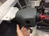
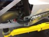
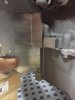
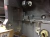
Heat is really an issue with mid engine cars. One of the areas this has been apparent is with the shifter cables. The plastic outer shell melts rather easily. With that in mind, I was able to get the shifter cables moved to the outside of the heat shields relatively soon after they emerged from the firewall. The cables are rather stiff, and the console positioning limits the angle of approach as the cables go through the firewall, so it is not really possible to run the cables along the firewall. The headers will be angling back as soon as they emerge from the cylinder heads, so there should be limited heat exposure to the shifter cables in there present position before they get outside the heat shield. To make sure, I will be adding heat shield tubing over the cables as they emerge through the firewall and towards the back when they get inside the heat shields for mounting to the transaxle.
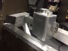
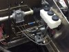
While I was in the area, I made a bracket to mount the overflow tank to the cooling system.
While I was in the area, I made a bracket to mount the overflow tank to the cooling system.
Attachments
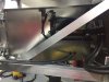
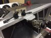
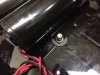
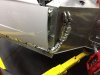
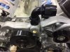
When I had the clutch installed and I made some room by grinding in the oil pan around the forward facing transaxle shaft, I noticed the rather large opening that exposes the flywheel gears to the environment. I could just picture dirt and debris getting in this area.
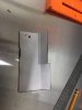
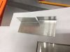
The correct this, I made a cardboard pattern to get the shape and the bends needed to close this space. Using some this aluminum sheeting, I made a shield to close off this space. I need to get the correct screw to install the shield, but it certainly will make this area cleaner looking.
The correct this, I made a cardboard pattern to get the shape and the bends needed to close this space. Using some this aluminum sheeting, I made a shield to close off this space. I need to get the correct screw to install the shield, but it certainly will make this area cleaner looking.
Attachments
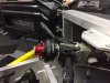
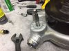
I ended the last session without having attached the protective shield that I made for the area around the forward facing transaxle shaft. I put that in, but had to customize a 3/8 bolt to be very short, 1/2 inch.
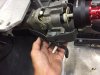
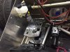
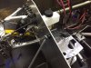
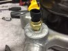
It is getting close to getting the motor put in, so I am finishing off the accessory drive, thermostat for the Speed Hut Gauges and the -20AN fittings for the water pump.
It is getting close to getting the motor put in, so I am finishing off the accessory drive, thermostat for the Speed Hut Gauges and the -20AN fittings for the water pump.
Attachments
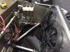
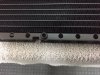
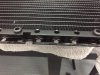
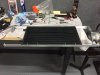
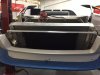
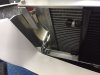
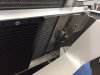
In thinking about the options in mounting the A/C condenser, I set as goals ideally having it be centered in the grill area of the car, since this is visible, and having there be at least an inch between the radiator and the A/C unit.
Rather than attach the A/C unit to the radiator housing, as is most common, I decided to make an independent frame for the A/C unit. Using rubber grommets in mounting to the frame, I made the frame from 1/8 X 1 aluminum angle. It worked great. A solid mounting, independent of the radiator, centered in the grill area.
Rather than attach the A/C unit to the radiator housing, as is most common, I decided to make an independent frame for the A/C unit. Using rubber grommets in mounting to the frame, I made the frame from 1/8 X 1 aluminum angle. It worked great. A solid mounting, independent of the radiator, centered in the grill area.
Attachments
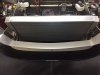

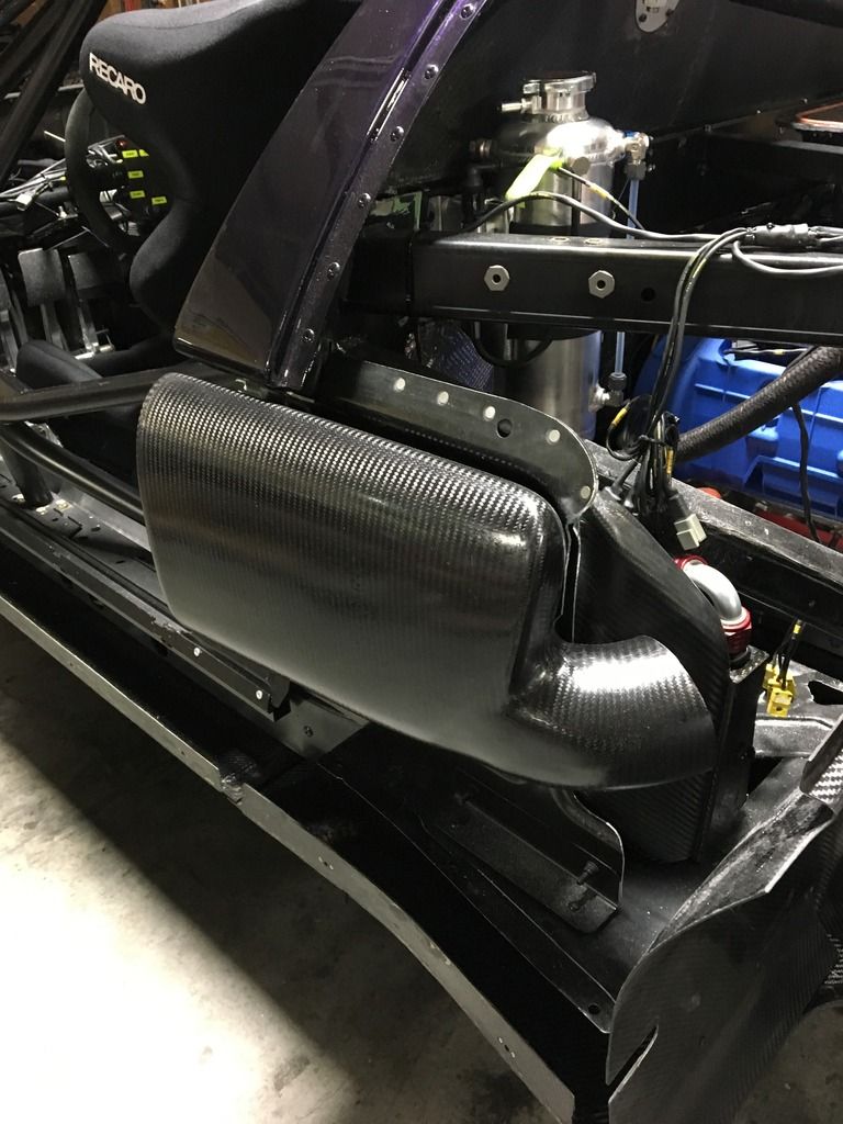
Mark I know its a bit late but we do have these.The enemy to air flow is turbulence, and the side scoop internal design causes significant turbulence. With that in mind, I added foam to the inner aspect, allowed it to cure, then trimmed it to the approximate shape that would resemble a water slide. After trimming, I painted on a coat of fiberglass resin to stiffen the foam. After a skin of body filler was applied and allowed to cure, I sanded as best I could and added a coat of flat black.
I had a chance to watch "Ford Gt: An American Icon" that was previously on the Velocity Network, now is in Amazon Videos. It is a great six episode program on the 2005-06 Ford GT. In one of the episodes, they interviewed the Robertson Racing Team, and in that interview they discussed the advantage the side scoops feeding into the air intake brought them. Hope it works. Even if it doesn't, it was fun to do.
And we have them in hand formed aluminum
Andy: Are these available? I think I need to change mine to get larger diameter tubing attached. What is the diameter? Where can I get these?
Mark
Mark
Andy: Are these available? I think I need to change mine to get larger diameter tubing attached. What is the diameter? Where can I get these?
Mark
Mark
Yes they are available, just would have to dig the moulds out, same as the fog lamp buckets
Outlet is 4" on the side ducts
H
Do you have fog lamp buckets? Any pictures or info?
Similar threads
- Replies
- 3
- Views
- 2K
- Replies
- 9
- Views
- 809
- Replies
- 5
- Views
- 941
- Replies
- 63
- Views
- 6K