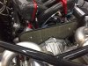
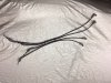
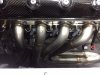
Thanks for following the build. There are so many ways to go with the exhaust. I wanted the muffler position and the exhaust tip position as top priorities. Steve, from Mannix Automotive in Naples, did a meticulous job laying the system out and the welds are perfect, in side (with Argon purging) and out. Steve wanted equal length to the headers on each cylinder, so the layout took some time, not having an example to work from.

- Forums
- GT40 Replica Manufacturers' Corner
- RCR Forum - RCR40/SLC/917/Superlite Aero
- The SLC Clubhouse
You are using an out of date browser. It may not display this or other websites correctly.
You should upgrade or use an alternative browser.
You should upgrade or use an alternative browser.
Mark's GT-R Build
- Thread starter mksetter
- Start date
I am working towards getting the interior finished and getting the interior tub installed. Ideally, I would have all of the holes drilled and everything laid out before adding the Damplifier Plus and the Luxury Liner. It is a pain drilling through the sound deadener materials.
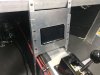
With that in mind, I wanted to get the entertainment system installed. Using the console panel I put in before putting the gas tank in place, I mounted a Kenwood 9903S. This unit has dual video inputs, Apple Play, Bluetooth and a number of other features that should make for a great sound system. Using recommendations from Scott R, I am putting in kick board 6.5" mid range speakers, dash mounted tweeters, then a 12" sub behind the passenger seat. I have JL Audio speakers on order with a JL Audio 600W 4 channel amp.
With that in mind, I wanted to get the entertainment system installed. Using the console panel I put in before putting the gas tank in place, I mounted a Kenwood 9903S. This unit has dual video inputs, Apple Play, Bluetooth and a number of other features that should make for a great sound system. Using recommendations from Scott R, I am putting in kick board 6.5" mid range speakers, dash mounted tweeters, then a 12" sub behind the passenger seat. I have JL Audio speakers on order with a JL Audio 600W 4 channel amp.
Attachments
Nice. Are you going to build the pods, or did you find a set that would work?
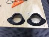
I found a set of kick board speaker enclosures, much like those Scott R suggested, on eBay and they are really well made and versatile. I will get photos. I plan to use a sub box from JL Audio designed for a pickup truck. It will fit well behind the passenger seat, since the seat has a significant recline to it.
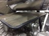
Keeping the engine bay looking good is always on my mind, and the heat insulation materials, although they might work great, look poorly finished at the edges. I ordered some vinyl edge trim to finish the edges of the insulation off. Now it looks like it should. I just hope the trim can withstand any heat it gets exposed to.
Attachments
In getting ready to try in the interior tub, I used Damplifier Pro and want to add Luxury Liner Pro for sound insulation. The Damplifier is self adhesive and is already in place. The luxury Liner requires contact cement to keep it in place. At this point I am just cutting and positioning. After I try in the tub, I will glue it in place. This stuff is really Quality!! Other than the exhaust sound, this car will be a coffin.
Attachments
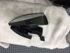
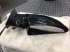
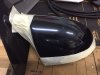
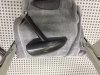
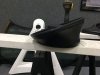
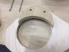
RCR provided me with some OEM mirrors, from which car I don't know, and provided the mirror housings for the GT-R. The trick is to see how the two go together.
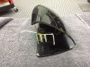
To find out, I started dissecting the OEM mirror and found that you really have to cut it apart. I knew I needed to save certain areas of the original housing, but was unsure of where the areas were that needed to be saved.
The first two photos are the OEM housing, untouched. The next three photos are the dissected mirror with the three mounting screws used to hold the OEM piece together. All of the unwanted materials were removed.
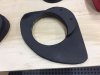
The next four photos show the other OEM mirror with the desirable areas taped off.
Fran did a great job of making an OEM mirror work. You just have to figure out how to make it work. It ends up that the outside of the OEM mirror, when trimmed properly, fits perfectly into the GT-R housing allowing it to be glued into the proper position.
To find out, I started dissecting the OEM mirror and found that you really have to cut it apart. I knew I needed to save certain areas of the original housing, but was unsure of where the areas were that needed to be saved.
The first two photos are the OEM housing, untouched. The next three photos are the dissected mirror with the three mounting screws used to hold the OEM piece together. All of the unwanted materials were removed.
The next four photos show the other OEM mirror with the desirable areas taped off.
Fran did a great job of making an OEM mirror work. You just have to figure out how to make it work. It ends up that the outside of the OEM mirror, when trimmed properly, fits perfectly into the GT-R housing allowing it to be glued into the proper position.
Attachments
-
 IMG_4097.JPG81.7 KB · Views: 455
 -
 IMG_4098.JPG78.7 KB · Views: 499
 -
 IMG_4096.JPG75.5 KB · Views: 427
 -
 IMG_4095.JPG74.4 KB · Views: 436
 -
 IMG_4094.JPG79.7 KB · Views: 514
 -
 IMG_4099.JPG55.5 KB · Views: 456
 -
 IMG_4100.JPG69.5 KB · Views: 433
 -
 IMG_4101.JPG68.1 KB · Views: 434
 -
 IMG_4102.JPG59.1 KB · Views: 483
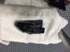
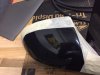
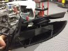
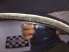
Here I am trying to show the trimming process. In the first photo you can see the screw mounting positions as they attach the mirror to the housing that you are trying to retain.
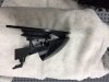
The second photo shows the metal framework that is the backbone of the OEM mirror. This needs to be cut off in the area I taped off with masking tape.
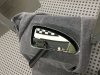
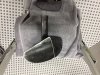
The next three photos show the trimmed OEM mirror. The OEM piece comes with an electrical connection that will allow for remote mirror adjustments. Since I will be the person driving this car 99% of the time, I elected not to utilize the remote adjuster. The wiring will be difficult to get down the GT-R mirror support post.
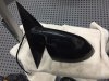
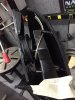
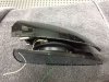
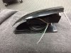
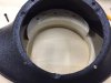
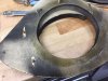
The next two photos show the GT-R mirror housings and the final three photos show the OEM mirrors positioned in the GT-R housings. If you look closely at the last photo, you will be able to see the GT-R housing, with the OEM housing just inside, intimately adapted to the interior of the GT-R housing. When I have the seats in place and the interior in it's final state, I will mount the GT-R housings, then glue the OEM mirrors in a position that allows for the best visibility. There is a little leeway in the positions the OEM mirrors can be glued.
The second photo shows the metal framework that is the backbone of the OEM mirror. This needs to be cut off in the area I taped off with masking tape.
The next three photos show the trimmed OEM mirror. The OEM piece comes with an electrical connection that will allow for remote mirror adjustments. Since I will be the person driving this car 99% of the time, I elected not to utilize the remote adjuster. The wiring will be difficult to get down the GT-R mirror support post.
The next two photos show the GT-R mirror housings and the final three photos show the OEM mirrors positioned in the GT-R housings. If you look closely at the last photo, you will be able to see the GT-R housing, with the OEM housing just inside, intimately adapted to the interior of the GT-R housing. When I have the seats in place and the interior in it's final state, I will mount the GT-R housings, then glue the OEM mirrors in a position that allows for the best visibility. There is a little leeway in the positions the OEM mirrors can be glued.
Attachments
-
 IMG_4103.JPG76.6 KB · Views: 504
 -
 IMG_4104.jpg84.1 KB · Views: 461
 -
 IMG_4105.JPG101.7 KB · Views: 464
 -
 IMG_4106.JPG109.4 KB · Views: 494
 -
 IMG_4111.JPG107.5 KB · Views: 506
 -
 IMG_4110.JPG100.8 KB · Views: 502
 -
 IMG_4108.JPG109.2 KB · Views: 442
 -
 IMG_4107.JPG101.3 KB · Views: 441
 -
 IMG_4109.JPG110 KB · Views: 450
 -
 IMG_4112.JPG58.4 KB · Views: 477
Hi Mark
I would suggest that you mount the mirrors as low to the body as possible it will reduce vibration as well as increase you field of view the closer you bring them to you. If you are going to bond them to the body and given that they have the long stalk you may even be able to push the stalk through the outer skin and attach the base to the inner skin greatly improving stability. The only reason we gave them the long stalk in the first place was that in the wind tunnel we found that the stock mirrors upset air getting to the wing by as much as 80lb
I would suggest that you mount the mirrors as low to the body as possible it will reduce vibration as well as increase you field of view the closer you bring them to you. If you are going to bond them to the body and given that they have the long stalk you may even be able to push the stalk through the outer skin and attach the base to the inner skin greatly improving stability. The only reason we gave them the long stalk in the first place was that in the wind tunnel we found that the stock mirrors upset air getting to the wing by as much as 80lb
Thanks for the insight. With the shorter stalk, getting the wiring down the stalk will be easier. Looks like I can wire up the remotes. Thanks H
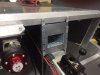
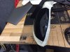
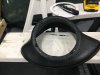
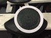
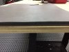
Today I started on the kick plate speakers. I ordered some speaker enclosures off eBay. They are the right size and have a great air tight seal when attached to a smooth base. With the template from JL Audio, the cutout was easy. This Snap-On air driven saw is perfect for detail jig saw type work. It works with such a small motion that is does not chip fiberglass gel coat. It can't be this easy. Well........
Attachments
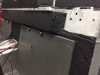
It ends up that the JL Audio speakers have the drive element longer than the speaker enclosure was designed to support. As photo 1 shows, with the speaker in place, the enclosure won't seat.
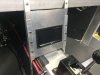
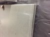
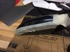
But it ends up that this was a good thing. The area I intend to mount the speaker will have Luxury Liner on the surface and I want to mount the speaker to the metal underneath. The thickness of the Luxury Liner is almost equal to the thickness of the 3/4 plywood needed to get the speak enclosure to seat. There will be carpeting on top of the Liner.
Making a base for the speaker enclosure out of plywood gets me the space I need, allows me to mount the plywood to the metal, then screw the speaker and the enclosure in place using wood screws into the plywood. The speaker enclosures will look fine having the Luxury Liner and carpeting to match the height of the plywood.
Attachments

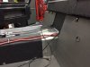
One last problem to solve before I can call this portion of the sound system complete. It ends up that it will take a screw 4 inches long on one side of the speaker to go thru the speaker rim and go the length needed because of the speaker enclosure to engage the plywood. My hardware only has 3.5 inch screws in a diameter that will work for the speaker rim.
The solution I used was to add a rim of additional plywood to the side needing the long screws allowing a available 3.5 inch screws to work.
The solution I used was to add a rim of additional plywood to the side needing the long screws allowing a available 3.5 inch screws to work.
Attachments
I am probably already half deaf from stereos and cars, but when I am driving, I prefer listening to the motor 90% of the time.
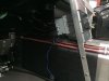
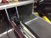
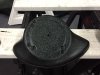
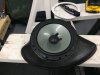
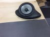
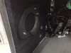
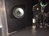
To finish what I started yesterday, in mounting the kick panel speakers, I want them air tight, so I used contact cement to start the seal, then stripped the butyl rubber from some left over pieces of Damplifier and used it around the mounting surface. The butyl rubber flowed nicely as I tightened the speaker mount in place, and oozed to the inside edges. Just to see how it looks, I added the speaker.
I have since removed the speaker until the stereo wiring is done and the interior tub is installed. I don't want anything to damage them.
I have since removed the speaker until the stereo wiring is done and the interior tub is installed. I don't want anything to damage them.
Attachments
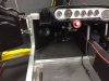
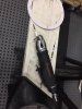
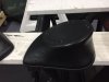
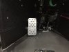
I made a dead pedal mount previously, but did not have the interior tub. Having the tub to make measurements from, I calculated the possible positions for the dead pedal, then sat down and picked the location. The photo seems to have distorted the position, but I will be glad to have it on longer drives.
Attachments
I am going to taking some time away from the GT-R project for travels to the Amazon and Machu Picchu. Will pick it up again when I return.
I returned from some travels and look forward to getting back in the shop. I received the final shipment from Infinity, so I should be able to attack the wiring. Not my area of expertise, so this could take a while.
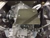
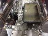
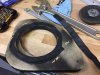
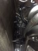
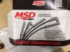
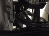
I was happy to be back in the shop working on the GT-R. I have a lot of wiring to do, so I started with the Spark Plug Wires. I wanted to reduce the stock look of the GM LS motor, so I remote mounted the coils. Naturally, this adds the issue of needing custom fabricated Spark Plug Wiring. I ordered an MSD kit for LS custom wires, which worked great. I started having all of the wires attached to the spark plugs, as you can see them hanging down under the car. I then revised the wire locations to get the shortest wire that came in the kit to the plug that had the shortest distance to it's respective coil. I was able to use the shortest wire at the length it came in the kit. Others needed to have the lengths custom cut, and all needed the coil ends attached. I added wire separators to the custom harnesses, then had to clamp the wires close to the block to keep them away from the headers.
Attachments
Similar threads
- Replies
- 3
- Views
- 2K
- Replies
- 9
- Views
- 809
- Replies
- 5
- Views
- 941
- Replies
- 63
- Views
- 6K