Mark's GT-R Build

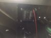
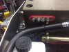
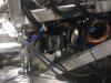
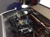
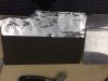
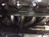
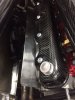
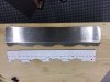
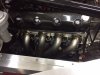
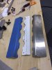
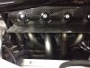
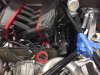
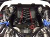
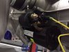
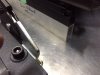
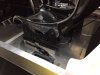
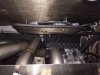
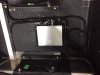
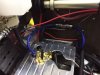
I also spent some time mounting the power amp to the sound system. I had it looking great, on the passenger side lateral heat shield, near the Holley Dominator EFI computer stuff, where I planned to put all of the electrical stuff..

Just as I was getting ready to wire it up, my friend Steve, from Mannix Automotive, came by and looked at it with a question on his face. He then pointed out that there needs to be about two feet of space between the Holley EFI control box and anything that could create electrical interference, such as the power amp.

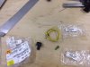
Thankfully he came by before I wired it up!

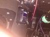
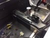
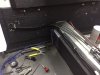
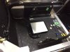
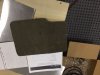
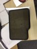
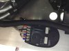
Now, I plan to mount it under the passenger seat, away from the Holley box and away fro the Kenwood receiver, but that if for next week.
 
Just as I was getting ready to wire it up, my friend Steve, from Mannix Automotive, came by and looked at it with a question on his face. He then pointed out that there needs to be about two feet of space between the Holley EFI control box and anything that could create electrical interference, such as the power amp.
Really? Is that documented somewhere? I wouldn't expect digital electronics to be that susceptible to interference, although there could be some analogue sensor inputs (which should use shielded cable). The only thing that would worry me would be ground noise.
 
I will look into it, but I can say that Steve is a pro car builder, specializing in drag racing. He does not usually put stereos in his cars, but he did talk about remote mounting the electronic shift controls away from the Holley Dominator box. Also, Kenwood did advise remote mounting the amp away from the receiver head unit, if that means anything.
 
I will look into it, but I can say that Steve is a pro car builder, specializing in drag racing. He does not usually put stereos in his cars, but he did talk about remote mounting the electronic shift controls away from the Holley Dominator box. Also, Kenwood did advise remote mounting the amp away from the receiver head unit, if that means anything.
Interesting. Perhaps Kenwood's EMI emissions are high. I would have hoped that they be well shielded, but, if it's digital, they might not care so much.
 
I have unpacked all of the Infinity boxes and laid it all out to see what goes where. It appears to be a great system. It is set up for the battery to go in the back, and I mounted mine up front, so some modifications will be needed.

I mounted the Master Cell in the driver side foot box wall, and the front Power Cell under the dash in that area. I used a good portion of the foot box wall on each side for speakers, so under the dash seemed like it will work.

The rear Power Cell fit great on the passenger lateral heat shield and the fuse box went just above the battery box in the front of the car.

I had a number of things that require a direct battery connection, so I opted to but a power strip just above the battery to simplify the wiring and make the appearance better.

I am just getting started with the wiring, so I have not really put any time into grouping the wires and putting them inside the black woven tubing.
 

Attachments

  • IMG_4606.JPG
    IMG_4606.JPG
    36.3 KB · Views: 322
  • IMG_4610.JPG
    IMG_4610.JPG
    26 KB · Views: 302
  • IMG_4605.JPG
    IMG_4605.JPG
    44.8 KB · Views: 359
  • IMG_4612.JPG
    IMG_4612.JPG
    46.6 KB · Views: 390
Hi Howard: What are these? You have me stumped. What are they? Where do you get them? Why have I not seen these? Or maybe I just overlooked them. Thanks for following my build.
 
I probably have too many things going on at one time. Wiring the motor, wiring the Infinity System, working on details of the interior, and starting to plan for the size oil cooler and trans cooler. We all look forward to starting the car for the first time, and all of these things need some level of completion to be able to start it.

In the wiring department, I have the front area wiring laid out, with the fuse box, the battery and the positive terminal pad in place. I have the Infinity Power cells having their power supply, as well as the main 1 gauge wire that goes from the battery to the starter and alternator. Also have a 4 gauge wire from the battery to the stereo power amp.

The interior tub allows for no room lateral to the center boxing around the gas tank, but there is some room between the metal and the tub on top. This allows for the shifter cable, etc. I am going to use this as a front to back wiring space. I have the Power Cell connector harness, the Power Cell power supply, the USB connection to the Holley Computer (that I plan to mount on the console by the stereo) that will allow for some programming the computer while driving, the DBW wiring to the throttle pedal, the heater control valve for the water pump outlet, the power amp power supply and the 1 gauge wire off of the battery running thru this area so far. I am sure there will be more wiring needing to go from front to back using this area.
 

Attachments

  • IMG_4619.JPG
    IMG_4619.JPG
    55 KB · Views: 355
  • IMG_4618.JPG
    IMG_4618.JPG
    44.2 KB · Views: 318
  • IMG_4617.JPG
    IMG_4617.JPG
    42.3 KB · Views: 304
I completed the spark plug wires a few days ago, but I did not finish the heat shields for the remote coils. I will only have two bolts to mount these shields, so I ran a vertical and horizontal bead to stiffen the metal. I have the size, then added the mounting holes, a layer of Second Skin Audio heat shield material, then added a layer of Lava Shield. I need to add edge trim (which I am out of), then I can put them in place.
 

Attachments

  • IMG_4613.JPG
    IMG_4613.JPG
    31.4 KB · Views: 326
  • IMG_4614.JPG
    IMG_4614.JPG
    38.4 KB · Views: 303
  • IMG_4615.JPG
    IMG_4615.JPG
    42.4 KB · Views: 281
  • IMG_4616.JPG
    IMG_4616.JPG
    66.9 KB · Views: 272
The heat coming off of the exhaust headers has been a concern in that it will certainly damage the carbon fiber valve covers. I confirmed this with Katech, the engine builder.

I headers look terrific, so I did not want to cover them, but I needed reduce the radiant heat and divert the heated air. So that being the goal, I mocked up in cardboard some heat deflectors, then fabricated them out if brushed stainless sheet metal.

I will be putting Lava Shield on the under side of the heat deflectors, but have to decide if I am going to leave them as brushed stainless, or put on some other finish.
 

Attachments

  • IMG_4628.JPG
    IMG_4628.JPG
    44.7 KB · Views: 317
  • IMG_4623.JPG
    IMG_4623.JPG
    32 KB · Views: 280
  • IMG_4625.JPG
    IMG_4625.JPG
    42.8 KB · Views: 305
  • IMG_4620.JPG
    IMG_4620.JPG
    47.8 KB · Views: 323
  • IMG_4621.JPG
    IMG_4621.JPG
    43.6 KB · Views: 291
  • IMG_4626.JPG
    IMG_4626.JPG
    49.5 KB · Views: 293
  • IMG_4627.JPG
    IMG_4627.JPG
    64.9 KB · Views: 307
  • IMG_4629.JPG
    IMG_4629.JPG
    58.4 KB · Views: 378
Continuing with the wiring, I ordered the parts from VW for wiring the solenoid for the starter motor.

When assembling, be sure to put some lubricant on the wire to get the boot over it. Perfect fit.
 

Attachments

  • IMG_4631.JPG
    IMG_4631.JPG
    42.2 KB · Views: 276
  • IMG_4632.JPG
    IMG_4632.JPG
    30.6 KB · Views: 289
  • IMG_4633.JPG
    IMG_4633.JPG
    38.6 KB · Views: 331

Howard Jones

Supporter
Those are linked washers used for the CV joint bolts. They don't turn under the bolt head and they are hard enough not deform under the torque loading. They are a standard part on Porsches and most race cars using CV joints also use them.

These are the size used on The larger/stronger size CV joint that is used on our cars.

You can get them from Auto Atlanta

FOR PORSCHE: 9P1501375, 9P1 501 375 - READY TO SHIP - (PLATE)
 
Last edited:

Howard Jones

Supporter
I would think so. Most if not all large size CV joints are the same. They are known as the 930 or Porsche turbo size CV's. If you what to be sure look for the part number on the CV joints you have and then call Auto Atlanta. Let me surf around and I'll see if I can come up with a link.

CV Joints 101
 
Last edited:

Dr. David

Lifetime Supporter
I would think so. Most if not all large size CV joints are the same. They are known as the 930 or Porsche turbo size CV's. If you what to be sure look for the part number on the CV joints you have and then call Auto Atlanta. Let me surf around and I'll see if I can come up with a link.

CV Joints 101

Thanks for the tip Howard....Do yo use these instead of the High-Collar lock washers on the Allen head bolts or in addition to them?
Thanks,
David
 

Howard Jones

Supporter
I installed mine in the same manner as the guys that run the blue superlight in the 25 hours at thunderhill and many other races in the NASA series.

Super clean CV bolts and driveshaft flange threads. Use blue locktight on bolts. Torque bolts to 58 ft/lbs installed using the link washers only.

I also have these on my GT40. They came with the kit more than 15 years ago. With 25k miles and hundreds of laps on the clock I have never had a CV joint bolt loosen.

The thing is, I think, the steel sheet metal cover on the CV joint deforms under the torque load of the bolts and then the round washer, or worse no washer, that might otherwise be used instead of the linked type turns reducing the tightness of the bolt until it loosens enough to fall off. A lock washer MIGHT work but I don't KNOW it works like the link washer/loctite system does.

The only other thing that would be better would be to safety wire the bolt heads. I couldn't see doing the work necessary to cross drill all those bolt heads and safety wire them when I could use a proven system and not need to do all that added work.

Loctite Threadlocker Blue 242 from Loctite Adhesives
 
Thank you, again, Howard, for letting me know about this. Like everyone else, I want things right, and this information certainly helps me get it that way.

This forum ROCKS because of the generosity of builders such as yourself. What a great group. I have learned so much from looking at all of the other builds and from the comments viewers have made on my build.

Before I knew anything, I started my build with developing the air intake from the throttle bodies to the body side scoops. Comments from Ken, and others, made me revisit that system. I now have an entirely different system I will be using, which will allow for WAY MORE AIR FLOW (all 4 inch diameter tubing and air cleaner intake and outlet), but I would not have known to do this if experienced builders did not make comments.

I thank you all for your help.
 
Up to this point, I have been developing the interior, seat position, console, pedal position, etc. without the body spider in place. When I placed the body spider in place, I realized how significant the height of the cowling at the base of the windshield is relative to the metal cross beam supporting the dashboard. With the body spider in place, I realized that my seat position was TOO LOW.

With the body spider and the dashboard in place, I decided that I needed the seat two inches higher than previously developed. With some 1 X 2 rectangular aluminum tubing, I raised the seat position for both the driver and the passenger. As a side benefit, the raised seat position got the headrest of the seat past the boxing made in the fire wall to accommodate the air intake, giving me a few more inches for seat travel on the Sparco seat sliders that I installed.

With the seats having their set position, I started installing the Power Amp to the stereo under the passenger seat.
 

Attachments

  • IMG_4638.JPG
    IMG_4638.JPG
    40.8 KB · Views: 332
  • IMG_4634.JPG
    IMG_4634.JPG
    37.9 KB · Views: 302
  • IMG_4635.JPG
    IMG_4635.JPG
    35.2 KB · Views: 267
  • IMG_4636.JPG
    IMG_4636.JPG
    40.6 KB · Views: 299
I started the heat shields for the remotes coils last week, but needed some edge trim, which has just come in. I don't know if the trim will tolerate the level of heat that it will get, but the coils should be fine now. I was not able to find heat resistant edge trim.
 

Attachments

  • IMG_4654.JPG
    IMG_4654.JPG
    43.7 KB · Views: 233
  • IMG_4655.JPG
    IMG_4655.JPG
    52 KB · Views: 243
  • IMG_4653.JPG
    IMG_4653.JPG
    53.8 KB · Views: 257
The wiring continues with the Power Amp and speaker wiring harness. The Power Amp is under the passenger seat, with the power cable coming from the battery, thru the fuse, into the interior, exiting the interior with the A/C lines under the passenger side dash, runs down the passenger rocker panel area, up behind the fire wall and into the rear of the interior behind the passenger seat. I am using 4 gauge wire for the power supply.

I am using JL Audio tweeter, midrange and sub speakers and their 600 Watt amp, so the cross over system is included. I mounted the cross over under the dash support beam on each side, just above the kick panel speakers.
 

Attachments

  • IMG_4657.JPG
    IMG_4657.JPG
    34.9 KB · Views: 274
  • IMG_4658.JPG
    IMG_4658.JPG
    47.6 KB · Views: 252
  • IMG_4659.JPG
    IMG_4659.JPG
    58.8 KB · Views: 276
Back
Top