
You are using an out of date browser. It may not display this or other websites correctly.
You should upgrade or use an alternative browser.
You should upgrade or use an alternative browser.
Parrots beaks & Quick lift Patterns
- Thread starter RacerDave
- Start date
Forget these. Thats GT Forte selling them. He's not very popular as you can read in another topic.
Pedro and Jimmy, both of those look correct.
I couldn't work out how they make them. best I could come up with was a welded structure as per what Jimmy shows.
The third angle projections are doing my head in, struggling to get them to line up.
the cad work that Pedro shows is fantastic. I don't know how you have done the folded formed curves. I'm looking at getting press tooling done at the moment.
Drawing number GT40P-1-2356 for the right side and GT40P-1-2357 for the left.
JimmyMac
Lifetime Supporter
Hi Ryan,
You might be thinking too hard about press tooling these.
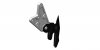
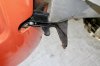
From memory the return bends are made from 3/4" X 3/32" thick flat stock from my model engineering shelf.
I formed them to the profile using a cheap Asian mini scroll bender tool that I got on eBay and final fitting was done with a bit of heat.
A big fillet weld inside stiffens them up a bit and these are stronger than the cold formed sheet method.
Ours were done this way originally and we changed them when doing the final fit of the rear shell.
You might be thinking too hard about press tooling these.
From memory the return bends are made from 3/4" X 3/32" thick flat stock from my model engineering shelf.
I formed them to the profile using a cheap Asian mini scroll bender tool that I got on eBay and final fitting was done with a bit of heat.
A big fillet weld inside stiffens them up a bit and these are stronger than the cold formed sheet method.
Ours were done this way originally and we changed them when doing the final fit of the rear shell.
Attachments
Last edited:
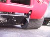
Question. Are any of the above functional. How are you strengthening the substructure to accommodate the weight you are attempting to lift. I'd like to install these on my CAV but don't see how to beef up the structure without redesigning the entire substructure.
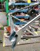
Pedro, awesome photo, thanks.
Tom, should be fine, its what was originally used back in the 60s. only lifting ~500kg/1100LBS. weight supported by 4 number small tubes in tension and compression. tubes don't need to be stiff as per it would for chassis stiffness, just below elastic failure point.
light is fast
Ryan
Tom, should be fine, its what was originally used back in the 60s. only lifting ~500kg/1100LBS. weight supported by 4 number small tubes in tension and compression. tubes don't need to be stiff as per it would for chassis stiffness, just below elastic failure point.
light is fast
Ryan
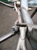
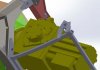
That is nearly there Ryan.
Rotate the cross bar to 45 degrees to get a better fit on your top struts and also the folded edge of you floor pan.
With a bit of heat you can fold the plate edge over a steel form just like the one in my last photo.
cross bar at 30 degrees from horizontal datum as per drawing
CL 2.03" in front of 115 vertical datum.
I have done my best to get the parts to line up as per drawings, but it is really hard to work out what angle the adjoining tubes are cut at. They list a bunch of measurements but they are on some abstract plane that's not apparent to me. Hence why my tubes from the lower bolt mounts come back at a funny angle. I have matched them to the angle on the mounting bar but they don't appear wide enough when you get back to the rear jacking points. I need to go an measure the width on my rear clip to see what width my rear cut outs are.
Last edited:
JimmyMac
Lifetime Supporter
Ryan,
That's exactly what I did.
My efforts were trying to make sure the body shell brackets fitted those two rollers easily, also to get the B pillar and bottom gaps right with the car length.
So I ended up drawing the pieces out full size and making a complete new frame - hence me mentioning rotating the cross bar a bit more to 45 degrees (approximate).
I also wanted the top of those lower rolled tubes to come off the chassis bracket in a flat square plane and hit the cross bar nicely. Like you mentioned the location of your cut-outs and the body shell brackets and how you shim them may determine the width of your cross bar and the included angles at the chassis end.
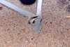
The chassis fab drawings are great to work off but it has been said before that all of these chassis' were slightly different and when I look a photos of FAVs final assembly jigs which were built of ply wood it makes me think that there was some workshop bodging going on. The fibreglass moulding tolerance was probably not too great also (I know for sure that mine wasn't)
Have another look at the first picture of the original pale blue chassis bracket that I posted above and you can see where someone has cut and re-welded the lower bracing to make it fit at a different angle. It could be an FAV assembly mod or a later repair but who knows.
I would stick to the drawings Ryan but be prepared for a bit of rework later on.
Keep at it mate, your doing a great job !
That's exactly what I did.
My efforts were trying to make sure the body shell brackets fitted those two rollers easily, also to get the B pillar and bottom gaps right with the car length.
So I ended up drawing the pieces out full size and making a complete new frame - hence me mentioning rotating the cross bar a bit more to 45 degrees (approximate).
I also wanted the top of those lower rolled tubes to come off the chassis bracket in a flat square plane and hit the cross bar nicely. Like you mentioned the location of your cut-outs and the body shell brackets and how you shim them may determine the width of your cross bar and the included angles at the chassis end.
The chassis fab drawings are great to work off but it has been said before that all of these chassis' were slightly different and when I look a photos of FAVs final assembly jigs which were built of ply wood it makes me think that there was some workshop bodging going on. The fibreglass moulding tolerance was probably not too great also (I know for sure that mine wasn't)
Have another look at the first picture of the original pale blue chassis bracket that I posted above and you can see where someone has cut and re-welded the lower bracing to make it fit at a different angle. It could be an FAV assembly mod or a later repair but who knows.
I would stick to the drawings Ryan but be prepared for a bit of rework later on.
Keep at it mate, your doing a great job !
Last edited:
I understand James. Some nights I spend hours and hours just looking a photos. None of them match, they are all slightly different.
Then you pick up 3 different drawings that are all supposed to go together and notice that there is inconsistencies, like three different values for the same radius.
So you go back to the photos and try and understand what was done.
Its like a big jigsaw puzzle.
I sent some files off yesterday to see if I can get some stuff cut out.
fingers crossed they were correct.
Ryan
Ian Anderson
Lifetime Supporter
What about these ones?
http://www.taylor-automotive.co.uk/Taylor-Automotive/Parts.html
http://www.taylor-automotive.co.uk/Taylor-Automotive/Parts.html
Before I start to re-invent the wheel again.
Where to get a full set, front and rear.
Quick lift parrot beaks.
Universal will work as I am at the point to fit my body and have some welding to do to make the mounting points.
Drawing will do also so I can have them cnc'd localy.
Where to get a full set, front and rear.
Quick lift parrot beaks.
Universal will work as I am at the point to fit my body and have some welding to do to make the mounting points.
Drawing will do also so I can have them cnc'd localy.
Similar threads
- Replies
- 3
- Views
- 1K
- Replies
- 14
- Views
- 5K
- Replies
- 0
- Views
- 220