Radiator Flow path Original Serck

Davidmgbv8

Supporter
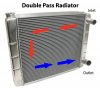
I am assuming that on the original cars that the hot coolant goes to the left inlet of the radiator and the cool out of the right. I assume that as the kenlow fan is on the right side. Can some one please confirm this is correct?
Thanks
 

Morten

Mortified GT
Supporter
B0D28A81-5058-4168-9A95-E35D0E14721C.jpeg

See where the radiator sensor id located, then you see flow direction through the pipes to & from the engine
 

Davidmgbv8

Supporter
So that is what noticed, and I figured the fan would be on the outlet side to make sure it is cool. But now rethinking, fan is on hot side and temp switch turns it on if cooling naturally does not work?
 

Morten

Mortified GT
Supporter
Fan switch is on hot side, thus switching on the fans if hotter coolant than the sender temp rating.
I’m using a temp sender at the engine for my Davies Craig waterpump and ecu
 
I concur, looks like the fan is on the hot input side.
what is not shown in plate D is the radiator air bleed line. This is shown in the Homologation papers or the FSAE papers. Cant remember which one.
Plate D is odd though, it shows the early MK I air bleed tank and heater as was common on the MK I road cars. It also shows the twin hot feed from the 8 stack intake manifold which was not used consistently across all road car. Need to check which way the water pump was configured as well.

A bleed line from the radiator was rarely used on the MkIs. Don't forget that the Parts List drawing is only applicable to the MkI road cars and is pretty accurate - there were variations as to where the water temperature gauge sensor was fitted and other slight differences; it is obviously only applicable to cars with the Weber set up; the Y-pipe was replaced with a single pipe on the Holley-equipped cars. The race cars generally used a different set up which sometimes included the use of Ricardo gas separators and the larger header tank; MkIIs were different again.

Regards,


Graham.
 

Randy V

Moderator-Admin
Staff member
Admin
Lifetime Supporter
Easy way to tell is this -
Water Pumps (mechanica) always SUCK.
There may be minor exceptions for some of the reverse-flow Johnny come latelys…
 
Hi: Does anybody know whether the GT40 radiator (RCR to be specific) is built symmetrically, in other words, does it matter whether the left or the right port is chosen for ``hot-in" (and the other for cool-out)?
(I suppose the unusual location of the hot-in port at the bottom is due to the mid engine design where the hot water from the engine is run to the front (above the cool water line) through the center tunnel. Hot water thus has to be forced down into the tunnel and it would not make a big difference to let it move up again at the radiator.)
 

Chris Kouba

Supporter
Hi Walter,

I think I put my feed on the side with the bleed screw on it to improve the odds of getting air out (in theory), but no, I don't think it matters which side is your feed or return.
 
I believe both ports are on the bottom because it is a dual pass design. Comes in one side, up and over and back out the bottom of the other side. I don't know why you couldn't use either side as the inlet.
 
Thanks for the comments. I asked because my car has the feed/in at the left and the out at the right (opposite to the diagram above and in some other RCR builds). The vent port (with a line back to the reservoir) properly sits on the top right - and a bleed tap (used when filling the system) on top left - so all seems well. Hypothetically directionality could have been built in the radiator to optimise flow.
Yes, the radiator should be of double pass design - rotated by 90 degrees (see https://help.summitracing.com/app/answers/detail/a_id/5279/~/what-is-a-“double-pass”-radiator? ). I live and learn ;-) ...
 

Attachments

  • double_pass.jpg
    double_pass.jpg
    38 KB · Views: 82
I am not convinced you need the vent port or that line. The Pantera is the same design from that era. They always show a vent back to the header tank but yet no one uses one nor do they exist. If you have a top bleed that would allow for purging air from the system. Better yet, get a vacuum fill kit and you will not have to deal with air at all. That is what all us Pantera guys have gone to. No more jacking the car's ass up in the air to fill it.
 
A Vacuum fill system evacuates the cooling volume. Not sure what a non-compressible radiator means as your block is also non-compressible. You draw something close to 30 in. of vacuum on the system and introduce coolant into the space until the vacuum has been eliminated. It is a CLOSED system that is evacuated and then filled in a controlled manner. I promise you there is no bubble of air hanging out in the top corner of your radiator once you pull 30 in. of vacuum on it.
 
How can a vacuum pull air from a non-compressible aluminum radiator if air is sitting at the top of an end tank?
I've drilled and tapped radiator end tanks for a M10x1.0 bleeder, I've done this now on 4 radiators and one heater core. Very satisfying psssst, then coolant to know that just about every mL of air is out of the system!

Dorman 902-112 Coolant Air Bleeder Screw Compatible with Select Models, 2 Pack https://a.co/d/hfeIcUL
It is a method for filling coolant into a closed system originally free of coolant- not a method for removing air pockets from an incompletely filled system. Compressible: watch what the hoses are doing under vacuum (in one of the several u-tube videos on this method) - ;-)

But yes it is remarkable! ``Vacuum" in this case does not mean zero !!! (air) molecules (we are not in interstellar space - would be too expensive :)) - in a closed !!! system these molecules do not disappear upon filling the system with coolant. However, the coolant as a fluid is so much denser than these relatively few air molecules. They do not matter since they tend to ``dissolve" more or less evenly (think as a fish) during the filling process (therefore ``no bubbles"). Later on there are still too few of them to form air pockets in remote areas of the cooling system. Hopefully, the one and only final air pocket sits in the fluid reservoir - which you can top up as needed under ambient pressure. This at least is my physical analysis as a non-expert ;-)
 
Last edited:
Back
Top