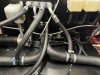
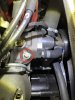
Anyone out there using this layout for their heater hose routing? I've got a T-fitting in the coolant line coming into the radiator (right side of the picture) going into the heater core, then back out into another T-fitting that joins the flow out of the radiator and back to the water pump.
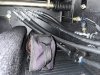
The result has been an intermittent heater that takes a very long time to warm up (long past when the coolant temp gets to 180 degrees) when it does decide to work at all. Yesterday, I got the car up to operating temperature and felt the smaller lines coming off the T-fittings into and out of the heater core -- both were very hot. But when I went to the other side of the bulkhead fittings, the lines (the two on the left side of the second picture) were cold to the touch all the way from the bulkhead to and from the heater core.
What I'm trying to figure out is if this is a result of air trapped in the heater core (a distinct possibility) or that these T-fittings don't allow the opportunity for coolant to properly circulate throughout the heater core. I can understand that on the high pressure side (coming out of the engine), the flow would easily make its way through the smaller diameter hose into the heater core, but it doesn't seem clear that returning from the heater core, the coolant flow would necessarily join the flow back to the water pump. I could see that being a"loop" of stagnant coolant. If so, would it help to have an angled fitting in place of one or both T-fittings so that the flow of return coolant out of the heater core would join the stream rushing back to the water pump at less than 90° angle?
Does anyone have experience with this set up?