Scratch Build of Jag XJ220 Replica

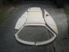
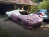
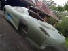
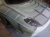
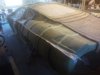
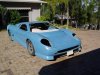
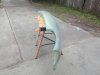
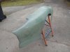
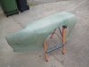
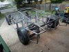
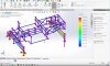
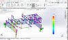
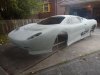
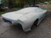
Here are a couple of images of the project I am currently working on. Its a Jag XJ220 replica and the pictures are of the 'buck' or model that will be used to produce the final panels. This buck will produce the mold which will then produce the final production panels (in fiberglass), sort of a 3 stage process. Have spent the last 2 1/2 years of part time work producing this model using cad and self designed cnc router to produce this shape. Now I have more time to spend on it and its progressing very well.

Hopefully this is the correct forum to post to, if not can the moderator advise.
 

Attachments

  • IMG_20200420_075302.jpg
    IMG_20200420_075302.jpg
    394.3 KB · Views: 1,734
  • IMG_20200420_080325.jpg
    IMG_20200420_080325.jpg
    338.4 KB · Views: 1,852
Fabulous!, I particularly love the "S" variant, one of my all time favourites.
What are your plans for the powertrain ? Perhaps the ford/jaguar V6 Turbocharged (as per the Noble M12) would be quite an authentic choice at reasonable cost. Please dont put a chevy ls in it :)
 

Joel K

Supporter
Nice project! Following along. Maybe a supercharged 4.2 liter from a 2009 or later XF would be a nice engine choice.
 
Here are a few more pics of this project. This shows the roof section parts that I routed by cnc and how they are attached to the body. The last 2 pics are fibreglassed over the buck to produce the final molds for the production panels. Have completed all the final molds except for the nose cone as this will require a complex process to make the mold.

Im not really thinking much about engines at this stage but I do like the idea of the Ford XF V8. This engine can trace its line back to the Jag V8?

I may try and document the build steps of this scratch build, it was an interesting design project for me to produce as it involved cad, cnc, software programming and quite a few challenges (and dead ends).
 

Attachments

  • IMG_20200128_074512.jpg
    IMG_20200128_074512.jpg
    394.9 KB · Views: 1,403
  • IMG_20200203_145658.jpg
    IMG_20200203_145658.jpg
    481.7 KB · Views: 1,563
  • IMG_20200317_133247.jpg
    IMG_20200317_133247.jpg
    457.1 KB · Views: 1,696
  • IMG_20200528_145937.jpg
    IMG_20200528_145937.jpg
    240.9 KB · Views: 1,297
  • IMG_20200528_150055.jpg
    IMG_20200528_150055.jpg
    235.5 KB · Views: 1,510

Denis Bedford

Denis Bedford
Clive I know how much work you are putting in to this project I did the same thing about 20 years ago, I got my XJ220 replica up to rolling with motor (jag V12) and transmission fitted and then sold it, wish I had not I have not been able to locate the guy I sold it to he also bought the moulds from me, probably sitting under a tree somewhere, I really love that car and I am very tempted to do it all again here are a couple of pics oops sorry only one of them would post
 

Attachments

  • F 024.jpg
    F 024.jpg
    476.1 KB · Views: 1,647
Thats a mighty example of an XJ220. Actually I remember that pic which I saw a few years ago when I was researching cars. My project is just about to move onto the panel making stage as the molds are almost complete and finalized. Your most welcome to come and have a look, I am located in Sydney so shoot me an email.
 
Here are some images of the cad for the router that I designed and built. But to backtrack, I found some cad of an XJ220 body on the web. Surprisingly there is a lot of cad files for exotic cars freely available to download. To convert to an actual shape requires a router and 3 pieces of software - a CAD program (eg Solidworks/Solid Edge), CAM software (eg FeatureCam) and a machine controller (eg Mach 3). I purchased a router to start making the model but this proved to be much too small for serious use (being 400mm by 400mm by 50mm). So I then decided to design/build something that was more suitable and ended up with a 1200 by 800 by 200 machine as per attached pictures.
The process for routing a part then becomes taking the XJ220 model and use CAD to split the relevant section, use CAM to define the tool cutting paths and then load these paths into the machine controller to route the part in XPS foam. This is a very simplified sequence and hope this covers the basic steps which I can expand if anyone is interested. It was very interesting and challenging to me to get this up and running.
I also took this a bit further and converted my router to a laser measuring device (using a laser distance meter with usb connection) I wrote some software to interface with the machine controller (Mach 3) and operate in the x and y planes and use the laser to measure the z plane to generate a coordinates file (which can be loaded directly into Solidworks to generate a surface). This can scan a car panel for example and return the coordinates.
Thats my 3 years on this project and no, I dont have a chassis for this yet. I have been thinking about this and am leaning towards a ladder chassis and I think I may be able to use a commercially available donar with suitable modifications. Denis Im not sure what you used but would be interested in your design.
 

Attachments

  • large mill table c channel _1.jpg
    large mill table c channel _1.jpg
    375.2 KB · Views: 1,345
  • largeZ and  X axis.jpg
    largeZ and X axis.jpg
    283 KB · Views: 1,152

Denis Bedford

Denis Bedford
Clive
The car in the pic had a space frame chassis made from steel rectangular and square tube with sheetmetal panels welded in place for critical parts like floors and firewalls with aluminium sheet in other places, however if I was to do it again I would probably copy the original XJ 220 chassis a little closer
 
An original version chassis would be a great match to this car. I also really like the idea of a space frame type chassis with bracing to produce a light but strong version by added complexity in key areas. At this point I'm still thinking about all this but as I am still producing panels haven't decided yet. I'm looking at double skinning the boot, bonnet and doors so any chassis design is still a bit ahead.
 
1st production panel!!
Its the front fender that I just pulled out of the mold. Only another 12 or so panels to make but very pleased after 3 years of work!
 

Attachments

  • IMG_20200707_141608.jpg
    IMG_20200707_141608.jpg
    553.1 KB · Views: 1,039
  • IMG_20200707_141615.jpg
    IMG_20200707_141615.jpg
    414.4 KB · Views: 1,123
  • IMG_20200707_141625.jpg
    IMG_20200707_141625.jpg
    426.2 KB · Views: 1,259
I really hope this is going to be available as a kit eventually, and not just a once off like Clives. (I remember when that was for sale!) I've been working on my own CNC plans for one of those eBay kits to do exactly this, but if I could just buy a prefabbed body, that would make my life a whole lot easier...
 
Have made much progress on this build, here are some completed work:
all panels manufactured
chassis cad completed
chassis built (see attached)
suspension and steering engineered and installed
chassis FEA started
engineering qualification started

Tom, I have the production molds completed and if you are interested in a set of panels then let me know. Email is [email protected]
 

Attachments

  • IMG_20210303_134221.jpg
    IMG_20210303_134221.jpg
    575.2 KB · Views: 1,032
I absolutely love this thread.....

..... In fact, it's the reason I joined the forum.

Clive, I'd be really interested in talking to you about a set of panels.... please keep an eye out for an email from me!
 
Completed part of the FEA of my chassis and here are some results.
For ICV compliance in Australia part of the test is is for torsion. The test requires 4000 Newtons (effectively 400 Kg) twist at one point with the other 3 points fixed. The requirement is to not exceed 1 degree of twist. This translates into displacement (using trigonometry to convert the 'right angle triangle' from the angle into a displacement). For my wheelbase I was looking at around 7.5mm displacement (equivalent to 1 degree) which I can comfortably meet.
The CAD Im using is solidworks which has a fantastic simulation section where this test can be set up and run. After a few iterations I now have great margin in my chassis and maybe can become a convertible?
 

Attachments

  • Rear FEA XJ220 Chassis.jpg
    Rear FEA XJ220 Chassis.jpg
    539.5 KB · Views: 891
  • Front FEA XJ220 Chassis.jpg
    Front FEA XJ220 Chassis.jpg
    501.2 KB · Views: 766
Back
Top