Spaceframe Chassis - variations

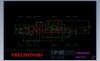
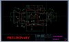
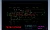
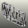
I am interested in doing a 'scratch-build' using a tube steel spaceframe. What I am asking for feedback is that there appears to be 2 variations of the tube steel space-frame. To define each, I have provided a CAD image of the floor-plan structures for each. (Spaceframe01 and Spaceframe02)
Spaceframe01 is quite ubiquitous and seemingly been around for sometime
Spaceframe02 is maybe somewhat newer and would be somewhat easier to fabricate based on a higher number of longitudinal members being parallel to the chassis axis, than Spaceframe01.
My major interest in the differences is the consequences on comparability of the MK1 fiberglass body components. The overlay I have attached reveals: -
1> Spaceframe01 is 1245mm (49") wide; while Spaceframe02 is 1150mm (45 1/4") - a difference of 95mm (3 3/4")
2> Spaceframe 01 is slightly longer between the wheel arches 1625mm (64") versus 1605mm (63 3/16")
3> There are other differences as seen on the overlay.
I am interested in advice on ensuring compatibility of body panels and chassis - I would be most interested in what spaceframe / bodykit combinations are out there ...

Regards
Mark
 

Attachments

  • Spaceframe_01.jpg
    Spaceframe_01.jpg
    108.8 KB · Views: 361
  • Spaceframe_02.jpg
    Spaceframe_02.jpg
    104.3 KB · Views: 382
  • Spaceframes_01_02_overlayed.jpg
    Spaceframes_01_02_overlayed.jpg
    71 KB · Views: 381

Howard Jones

Supporter
Make some comparisons to the bottom of the spider and front and rear body pieces to get an idea how wide it needs to be. You can't change the body mounting points much as far as width goes. There does seam to be a significant difference in over all widths as well as lenghts. That makes me wonder as nearly all GT40 body's are very close to the same width and lenghts.

Do you have a body? Without one in hand your are committing to a lot of chassis construction work and not knowing if the body will fit.

Bob is correct however, without seeing a complete set of plans I couldn't offer what little value my advice would be worth.
 
Without some indication of what's happening in the vertical plane, it's impossible to properly evaluate either design.
Thanks Bob ... yes, I fully understand the need for the 'whole picture' for constructive comment.
I shall provide drawings of each in a post below and would welcome your comments.
 
Make some comparisons to the bottom of the spider and front and rear body pieces to get an idea how wide it needs to be. You can't change the body mounting points much as far as width goes. There does seam to be a significant difference in over all widths as well as lengths. That makes me wonder as nearly all GT40 body's are very close to the same width and lengths.

Do you have a body? Without one in hand your are committing to a lot of chassis construction work and not knowing if the body will fit.

Bob is correct however, without seeing a complete set of plans I couldn't offer what little value my advice would be worth.
Thanks for comments Howard ...
Yes .. I might need to get at least the Spider as it would define the widths
The basis of the two chassis is further detailed in the two posts below ...
I would agree and expect what you state : "... There does seam to be a significant difference in over all widths as well as lengths. That makes me wonder as nearly all GT40 body's are very close to the same width and lengths ..."
 
Last edited:
This is the chassis I refer above as 'Spaceframe_02' It is characterized by being somewhat narrow 1150mm / 45 1/4" at the floorpan (Dwg: 0-level)
Chassis width at top of sideframe is also narrow at 1630mm / 64 3/16" (Dwg 1-level)
Depth is 254mm / 10" (Dwg: 1-level)
 

Attachments

  • Chassis drawing - 0 level .pdf
    37.5 KB · Views: 333
  • Chassis drawing 1 level .pdf
    29.7 KB · Views: 264
  • Chassis drawing 2 level view.pdf
    44.6 KB · Views: 272
  • Chassis drawing lateral view.pdf
    36.5 KB · Views: 294
  • Chassis 3 D front view.pdf
    43.3 KB · Views: 253
  • Chassis 3 D rear view (2).pdf
    45.9 KB · Views: 242
The chassis I refer above as 'Spaceframe_01'
Width at floorpan is 1245mm / 4' 1" (Dwg : Frame03c)
Chassis width at top of sideframe is 1727mm / 5' 8"
Depth is 248mm / 9 3/4" (Frame03b)
 

Attachments

  • GT 40 Frame031.jpg
    GT 40 Frame031.jpg
    30.1 KB · Views: 387
  • GT 40 Frame032.jpg
    GT 40 Frame032.jpg
    28.5 KB · Views: 339
  • GT 40 Frame0302.jpg
    GT 40 Frame0302.jpg
    31.8 KB · Views: 312
  • GT 40 Frame0303.jpg
    GT 40 Frame0303.jpg
    32.5 KB · Views: 328
  • GT 40 Frame03sv.jpg
    GT 40 Frame03sv.jpg
    30.3 KB · Views: 311
  • GT 40 Frame03d.jpg
    GT 40 Frame03d.jpg
    32.8 KB · Views: 309
  • GT 40 Frame03e.jpg
    GT 40 Frame03e.jpg
    28 KB · Views: 316
  • GT 40 Frame03f.jpg
    GT 40 Frame03f.jpg
    26.7 KB · Views: 364

Howard Jones

Supporter
Well if I had to comment on the two then 01 has many more triangulated structural boxes than 02. But even then it seams to missing a lot of the transverse triangulation elements as well as most if not all the horizontal. Proper triangulation is the foundation of a sufficiently stiff chassis. Both of those plans lack a complete triangulated design.

Example of what I am referring to:
 

Attachments

  • large.png
    large.png
    137.4 KB · Views: 331
Last edited:
Mark, all those dimensions are variable anyway. I have used the second plan for a road going M8B constructed from 40mm sq 2mm tube and have found it to be exceptionally strong. One main change I did was to fabricate the centre tunnel section from 1.6mm sheet with a tack welded bottom plate. All my water and surplus wiring runs up that tunnel.
 

Attachments

  • DSCF3669.JPG
    DSCF3669.JPG
    374.4 KB · Views: 317
  • DSCF3688.JPG
    DSCF3688.JPG
    293.4 KB · Views: 315
  • DSCN1462.JPG
    DSCN1462.JPG
    457.2 KB · Views: 313
  • DSCN5971.JPG
    DSCN5971.JPG
    374.1 KB · Views: 315
  • DSCN5976.JPG
    DSCN5976.JPG
    197.6 KB · Views: 295
If you make the bottom of the seating area a bit wider it will give you some freedom and room to move when it comes to seat sizes. The down side to this is that the side sills get narrower so your fuel tank size will go down.
If the make the length of the side sills a bit shorter between the wheel centers, then you get a bit of wiggle room when it comes time to align all the panels front to rea and left to right. Some of the bodies are a bit shorter on one side than the other, or you might have to push one sill forward and the other backwards to get the doors/front clam and rear clam to all align.
If you move the outer upper edge of the side sill in then you will get a bit of wiggle room when it comes to setting the vertical alignment of the sill against the closed door skin.

The key points you are missing are

1 The distance of the front edge of the scuttle forward from the front edge of the side sill.

2 The position and angle of the rear roll hoop

3 The width and height of the rear window. You don’t want to have any tubes going through that. I would leave these last two until I had the body fit up before welding them on as even a small angle change makes a big difference. Kit manufacturers would have this all worked out and set via a jig to make sure that its spot on.

I am still to confirm these items for my build, but think that they may vary slightly for the different bodies. I plan on building a basic structure and assembling the bodies onto it before I go to much further.
I would also put the center tunnel off center as it helps with getting the water pipes in while avoiding the front pulley on the engine. Making this ~3” wide and setting one side of it on the center line of the chassis seems sufficient.

Regards Ryan
 
Back
Top