Troy's 5 year Build

Troy, curious on using the ms3 and getting gauges to work successfully and integrating to all the other things (e.g. steering column for turn signals etc) Are you still going to use the InfinityBox stuff (rebrand isis)? really curious how you will approach the electronics.

That is an interesting question as I had two wiring failures on my race car and ripped every wire out and started from scratch with everything new and with what I learned I feel very comfortable making a high end motorsports complete car harness. I have not used the ISIS system, but in theory it should work just fine. I guess when I get close to that I will open that box and see if I use it or not.

I know at first I will just have a battery and have the MS3 pro wired up at a temporary system I will wire in later and will do this to tune it and get it all up and going.

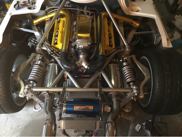
Tonight I am working on designing a new intake manifold. I was going to go with stock, but the design is so terrible, runners so long and bad shapes, so restrictive, very tall, TB barley fits under the engine cover. It is also just not pretty.

The new intake will be sheet metal alum TIG welded with short straight runners and velocity stacks. I will use a single 92mm LS TB that includes the IAC. I will face this towards the transaxle as it makes intercooler plumbing much easier.

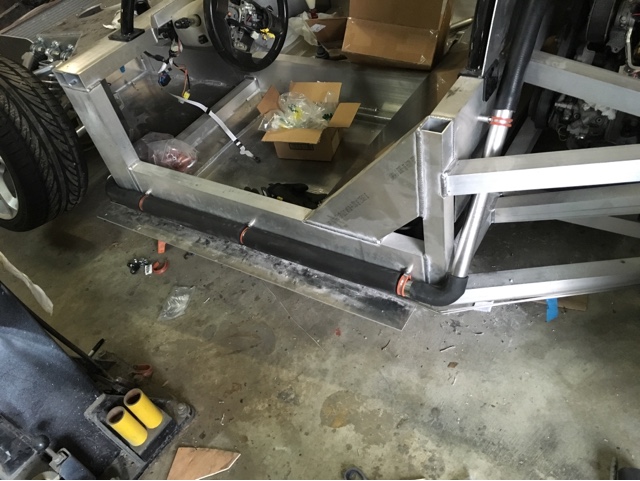
I also just got the coolant pipe bead maker from DOC and will be routing all the hoses here very soon. I got a bunch of 1.5" SS mandrels to weld up and also got of a bunch of 1.5" hoses from PEPboys with different sizes and shapes to make it all work.

I also got an inline 1.5" with rad cap on it and that is the high point of the system and will keep it simple. Then I can just get a $10 overfill container from PEPboys and will work just fine. I wonder if the radiator has something on the top of it as an air bleeder? If not I will need to add one, or just a small hole with a screw in to bleed the air. This way it is the same as the MR2 I am used to.

I will take some pictures of the intake once I get a mock up. I am making it out of carboard at first, hehe, to see how it all fits and will work before I jump into all the work with the alum.
 
No good pics yet and I am going to VIR for a race tomorrow.

I did cut up a lower 1uzfe intake and figured out how I am going to make it. I made a carboard rectangle that fits very nice in the area and is good and low to fit under the bonnet plexiglass. The runners will be nice and short and the intake plenum will be the correct volume size compared to the engine volume. I figured out the overall layout and dimensions, I just need to figure out the exact shape of the top for this portion. It will be all alum and TIG welded so I might leave it Alum like this, polished alum, powdercoated or a CF cover. We will see on that how it comes out overall. I also need to make the velocity stacks and work on the tooling to make these. It will be a two part press process to make these (lower and upper) with heat to get the correct shape. I have made them before and once the tooling is made it is not that hard, just takes time. That will take most of the time for sure. This is exciting and the fun part of building for me, the making of crazy new items. This intake is made for higher rpms for my later stage full engine build for 9000rpm.

I also need to get a new mill as the motor on my old tabletop one went and will cost as much as a used mill. I see a few on CL I might check out on Sunday if time permits.
 
Here is the basic shape and design for the intake. Now I am waiting on materials and will have it all TIG welded up. This will look the part of a high end custom alum intake. I will work on the velocity stacks this week and have it done in a few weeks. Also, the total runner length will be 8", 4" head and 4" intake. On my computer engine simulator it will lose about 30hp down below 3000rpm, but on our lite cars I am not worried. The good part is that it will gain like 80hp at 7000 rpm and more beyond that as the stock intake is so terrible.
blogger-image--1082118563.jpg

blogger-image--868096899.jpg
 
Nothing very exciting. I finally figured out my coolant pipes and routing. I did a hybrid approach to hoses and SS mandrels. Around the front wheels I used SS mandrels and will TIG weld them up. Then a 45 degree around a bend by the body to go down to the back.
blogger-image--1174925917.jpg

blogger-image--911712977.jpg


Also routing the brake lines as I go.
blogger-image--787753497.jpg
 
BTW- valves covers and calipers are all off and at FAP Auto getting powedercoated bright porsche yellow. I am undecided on what to do with the intake color choice, just alum TIG welded, Alum TIG welded polished or powdercoated also. Time will tell on that one.

Tonights job is to TIG weld up the front pipes.

BTW- DOC's bead maker works great.
 
I am routing coolant lines and brake lines and go to the back and this just does not seem to fit right at all. The front was a little bit off and I can deal with that, the sides matched up for the angles and all and then when I get to the back it does not seem to make any sense where the location of these bends are. Am I missing something here or did the guy who made them just have a really really bad day? I am hoping to not have to buy new brake lines and clutch line and bend and flare if I do not have to, but it sure looks like that way. Thoughts?
blogger-image--963454074.jpg
 
I also finally got my coolant lines and hoses figured out and happy with how it came out. I purchased some SS mandrels and welded them up. I am not a pretty welder so I will wrap these in heat wrap or something up front to hide the ugliness. It is a clean install though. I have a good idea of how to run the heater core lines to and from and also the twin turbo water coolant lines to both. The SLC might seem like a big car, but once you stuff a V8, transaxle, twin turbos, twin intercoolers, oil cooler, trans cooler, accusump, it gets small very quickly.


blogger-image--798364809.jpg
blogger-image-2032012630.jpg

blogger-image--219389949.jpg
 
I am hoping to not have to buy new brake lines and clutch line and bend and flare if I do not have to, but it sure looks like that way. Thoughts?
If you look at the pic below, you can see how I routed the brake lines on top of the rails. This pic is of the right side, and I think your lines are routed differently down sides of the car. But on that section you may be able to tell how I made the transition around the vertical support. This is how my brake lines were taped to the car when it was delivered. If you have some slack in your lines, you may need to pull them aft a bit to get the bends in the right spot. If that doesn't do it, is it possible the lines are on the wrong side of the car?

2015-07-31-07.jpg


Good luck in your race this weekend. I hope the snow doesn't spoil the event. See you there!

A.J.
 
Pete- Mine are pretty close to yours so I guess I will just work with it. I can change some of the angles on the pic below to make it longer to try to fit OK. Just odd that we would have these curves so far away and not curve into anything. At least I am not going crazy here. My car is an earlier car so maybe they fixed it in later cars.
blogger-image--660326815.jpg


On the pass side do you guys run the line on top of the alum frame or on the side?
blogger-image--1094716214.jpg

blogger-image-1657411762.jpg
 
I made a tool to make the velocity stacks for the custom intake. Took some time to get the curve just right to flare out the alum with the correct curve, but I am happy with how it has come out now.
blogger-image-1934051531.jpg

blogger-image--1090429476.jpg
 
Here is a quick update. I know, I am slow at this get this car done thing. My race car team takes up most of my time.

I designed and made up the intake and then sent it to a buddy who is way better at TIG welding than me to make the intake pretty. That took a lot of time to make it just the way I wanted to with performance parameters to consider and fitment in the SLC. I used my engine simulator program to help design the size of the plenum, runner diameter and runner length to optimize the hp and hp range I am looking for long term as I plan to rev to 9,000 in the future.
blogger-image-1316750089.jpg


I got the valve covers powdercoated Yellow and they really look good in there.
blogger-image--1607050345.jpg


The intake is nice and center for the highlight there when done under the plexiglass. I plan to polish it up as it looks good as is.

blogger-image--1481829839.jpg


Now this upcoming weekend I will be working on the exhaust manifold. I got the Borger Warner EFR 6258 turbo internal wastegate V band clamp and internal blow off valve with T4 twin scroll inlet housing. This turbo is truly amazing for what it can do, how fast it spools up and how efficient it is. After a bunch of math and figuring out which cylinder needs to go to what side of the turbine inlet to get the most out the twin scoll it is finally figured out on a math point of view, now on to making the manifold. I will also be using an Alum MR2 Turbo intercooler on each side and the fitment is very nice. The plumbing of the intercooler pipes will take a little bit of work, but all can be done now. There is not a lot of room to work on the exhaust and items there so you really have to think ahead when figuring it out. I also decided to make my own fuel rails to get enough fuel in there and be fine long term.

Slowly she is getting there.

I also got my Brembo Calipers powder coated and they look amazing in person.
blogger-image--1244348129.jpg
 
I did just press them, but there was a bunch of trail and error to get the shape of the press right as it was splitting them at first. If you try to go too fast or too long it will split the alum. I was on the borderline as I would split like every 5th one made. The intake runners are all ported and now will have amazing smooth flow. One of the main downsides to the 1uzfe engine is the intake design as it was super long and went from round to oval to round to an oval curve to a round 180. They were like 14-16" long in there also and with the 2-3" in the head itself it was made for like 2-3K rpm. The intake will really liven up the engine and be able to rev where I want to go.
 
Quick update, nothing major. Intake plumbing, intercoolers mounted, intercooler fans mounted, turbos mounted. I redid the intercooler piping like 5 times to get it where and how I liked it. I used the gold reflective tape on the piping and intake. It might be too much on the intake as there might be too much yellow. I can take it off later and polish it if needed. I figured out the fuel system components and will do all the an hoses to connectors this weekend, I hate those. I got a pair of 6" round straight through dynomax mufflers. There is not much room above the axles, but these fit. Single 4" tip will come out the back on each side of the license plate. More on that after the weekend. Very slowly getting there. Goal is to have her engine running springtime.

blogger-image-864825964.jpg
 
Looks cool! I personally use the aeroquip push lock fittings. Very quick, cheaper, and less chance of an incorrect install. Simplifies it all abit and easier to disassemble without the chance of creating leaks in the process.
 
blogger-image-1146670527.jpg

Quick update. Exhaust figured out and rear tac welded in as I might have to move the tips a bit when the body fitment is final so I am trying to think ahead on some things. Cooler are held in with temporary brackets for placement and will be redone with stronger alum ones. Turbos fittings are all done and figured out. Oil in, oil out, water in, water out, heater core figured out and I just looped it into itself for now. Fuel lines are all done and figure out and still debating on fuel tank vent line. There are a ton of an lines on this setup and I got the Koul tools (if anyone wants to borrow them and just pay shipping let me know) as they make it much easier to install. I plan to make some heat shields for the mufflers to keep heat away from the shocks. I also put a V band right before the mufflers as I might change the muffler type and size depending on what it sounds like and I might need to add a CAT at some point.

Next goals
1- Make a custom oil catch can and I plan to mount it high on the rear firewall and then drain back into the heads. I might just put the two lines in and then no check valve to let it drain in as needed with a breather filter on top. Just something small.
2-Brakes, I have not done them yet and need to do that.
3-Throttle cable adapter at the pedal. I got a Lokar custom 12' cable and will see how to adapt up a bellcrank arm on the gas pedal. I have some ideas and will see how that goes.
3-Clutch line and fittings with brake setup.
4-Make a moveable base plate for the pedals so I can move them forward and back as I am only 5-6. Ordering the alum today for that.
5-Mount the rad fans.
6-Mount the ecu, MS3PRO, on the rear firewall and start to wire her up. I plan to make a quick test switch fuse panel for now for testing and dyno. Then later will do the MOTEC PDM setup and switches when I go crazy with the interior.

It might not look like a lot done, but a lot of little things figured out and getting there, still slowly, but progress none the less.

Troy
 
blogger-image--1986838651.jpg

Side mount intercooler. I might paint it black, but the silver looks good also. I had to the cut the body a little bit to fit, but it looks good. The intercooler fans will be controlled by the MS3PRO to go on at like 3-5psi of boost along with the oil cooler.

Here is the fuel system figured out. Radium surge tank with built in pump to handle the fun. I plan to make an access panel if needed for filter changes.
blogger-image--814523440.jpg


Here is the rear end. The tips are in to the center (and a bit low right now) as I plan to use different taillights in the future and will be redoing the rear a bit to make it all work. New different headlights also will be used. You all inspire me on these things.
blogger-image-1149921776.jpg
 
Back
Top