Chuck and Ryan's RCR Build

Chuck

Supporter
Audi to ZF Conversion - Shifter

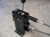
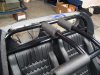
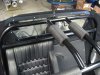
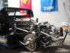
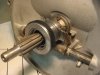
The shifter box used with the ZF is substantially larger than the one used with the Audi 016. The ZF has longer throws, the box is a good half inch higher and a half inch longer. It also has a different mounting flange arrangement. We decided to mount it in a way that would not require drilling any new holes in the center tunnel particularly since the coolant and AC line are filling up that space.

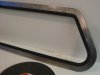
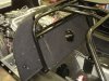
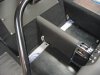
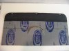
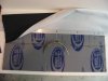
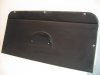
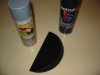
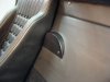
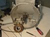
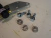
The parking brake handle is supported by steel brackets that bolt to the floor. Those brackets are ideal for mounting the shifter box. The mounting tabs on the front and rear of the shifter box were not used. Once the position was determined, holes were drilled and quarter inch bolts were used to secure the brackets to the shifter box. The brackets are mostly concealed from view by the seats and carpet, but we painted them the usual low gloss engine black to protect against rust.

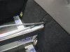
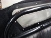
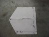
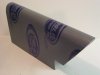
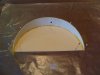
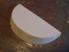
The passenger side of the bracket is pushed up tight against the center tunnel because the seat fits very snug on that side. This leaves a half inch gap between the tunnel and the bracket on the driver’s side. A piece of black marine polymer board was cut to fill the gap, making a nice snug fit. Once bolted down the shifter was very snug, so this spacer board is probably not necessary.

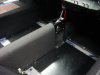
The shifter box was located 19 inches from the firewall, measured along the tunnel.

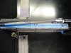
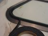
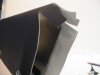
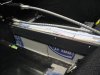
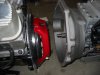
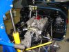
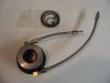
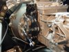
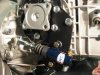
The shifter cables were routed through the same hole in the fire wall that had been used for the Audi cables. Three foot sections of 3/8” rubber fuel line hose were slit and placed over the shifter cables to prevent them from chaffing. About six inches of the hose extends into the cabin and two and a half feet into the engine compartment, providing good protection as the cables run along the right side of the engine just above the oil pan.

Another step closer to dropping in the drivetrain . . . .
 

Attachments

  • ShifterSupport1.JPG
    ShifterSupport1.JPG
    128.8 KB · Views: 648
  • ShifterLocation.JPG
    ShifterLocation.JPG
    141.3 KB · Views: 684
  • ShifterCableCovers.JPG
    ShifterCableCovers.JPG
    189.8 KB · Views: 539
  • ConsoleShifter.JPG
    ConsoleShifter.JPG
    134.9 KB · Views: 589

Chuck

Supporter
Rear Window

Now this is a really good upgrade.

The rear window between the passenger compartment and engine as originally supplied by RCR is a plastic material (polycarbonate??). Ours was damaged by hot fuel sprayed from those pesky Weber carbs before they were tuned. When we visited RCR in September, Fran had just received some real glass windows, so that was yet another item added to our shopping list. The glass is double laminated and about a quarter inch thick. This would be a real improvement, not likely to be damaged by hot fuel, less likely to scratch, perhaps a bit more sound isolating, and easier to clean.

In order to replace the rear glass the spider had to be removed: no small task. But with two doing the job it was not difficult to lift it off the car, giving us access to the screws holding the rear window in place.

The aluminum frame was painted low gloss engine black on the exposed interior side. McMaster-Carr (www.mcmaster.com) makes a neoprene foam rubber strip 1/16” thick and a half inch wide. Part number 8694K11. This was placed around the firewall to ‘cushion’ the glass. The same material was placed on the glass side of the aluminum frame. Once the glass was set in place, a strip of rubber foam weather seal, 3/8” x 3/16” thick, was pressed around the glass where it contacts the frame. This was to help hold the glass in position until the screws holding the frame were tight. DO NOT over tighten the screws. We used button head screws with nyloc nuts, tightening until snug.

The carpet around the glass was carefully pushed back so that it was just outside the perimeter of the glass, but under the frame, as the frame was being installed. Avoid any carpeting getting under the glass or the glass will not seal up tight.

This little project really makes a difference. We much prefer the aluminum frame painted black. It gives it a more finished look.
 

Attachments

  • RearGlass1.JPG
    RearGlass1.JPG
    177.6 KB · Views: 692
  • RearWindow1.JPG
    RearWindow1.JPG
    95.2 KB · Views: 620
  • RearWindow2.JPG
    RearWindow2.JPG
    112.4 KB · Views: 589
  • ReearWindow4.JPG
    ReearWindow4.JPG
    126.9 KB · Views: 592
  • RearWindow6.JPG
    RearWindow6.JPG
    187.1 KB · Views: 681

Keith

Lifetime Supporter
Chuck,
I actually did something similar for the bulkhead window on my car. I had a piece of 1/4 inch laminated glass cut at a local glass shop (for $29.00) and I sandwiched it with RTV between two window frames that Fran provided. The inside frame I had powder coated gloss black and the outside frame was coated with the bed liner material to match the bulkhead. I think it looks great.

I have been away from the forum for a few months now but I am finally moved into my new shop and I plan on finishing up my car over the Holidays.

Best of luck with your new transaxle project.
Keith
 

Attachments

  • GT 40 013.jpg
    GT 40 013.jpg
    144.3 KB · Views: 754

Chuck

Supporter
Tom:

Perfection is an elusive goal that much more accurately describes your GT than mine. But thanks regardless!

Keith:

Yours is looking very good. Like the sill treatment.
 

Chuck

Supporter
Center Console

Since the shifter cables set higher with the ZF shifter box, the center console previously used would not work. A pattern was made for a replacement.

It is designed to set on the floor. It simply drops in place without any screws or hardware securing it. On the driver side a half inch spacer was made from black marine polymer board so that the console would sit evenly behind the shifter box. The console was made from .040 aluminum. Once cut to shape it was covered with Cool It sound dampening mat. We found some vinyl that matches the leather seats at a fabric store which was used to finish the job. The vinyl was cut about two inches over sized, the flap folded over the back side, and then secured with contact cement on the inside only.

The console stays firmly in place but can be easily lifted out should there be a need to access the shifter cables.
 

Attachments

  • CenterConsole1.JPG
    CenterConsole1.JPG
    104.3 KB · Views: 467
  • Console5.JPG
    Console5.JPG
    91.2 KB · Views: 436
  • Console6.JPG
    Console6.JPG
    80.1 KB · Views: 485
  • Console7.JPG
    Console7.JPG
    159.8 KB · Views: 506
  • Console8.JPG
    Console8.JPG
    161 KB · Views: 581

Chuck

Supporter
Fire Wall, Part I

Some modifications were made to the fire wall, seeking a simple, more prototypical arrangement than we had used before. The fire wall was covered on the engine side with silver heat resistant material. The passenger side was covered with a layer of Cool It sound dampening mat.

Vinyl which was an exact match for the leather seats was used to cover the fire wall. It was covered in two sections due to the bend near the top of the fire wall. First the top portion was covered. The vinyl is secured with contact cement on the reverse side.

An aluminum strip was used to secure the upper edge of the vinyl used to cover the lower portion. It was held in place with short, counter sunk screws. The fire wall was drilled and taped so none of the screw would protrude. As the vinyl was secured in place it was pulled snug, left to right, so no creases would remain. A one inch flap on the sides and lower edges were glued to the engine side. Always glue only the edges on the back side only.

The bump for the water pump pulley created a separate problem. After the vinyl was secured in place, a slit was made along the hump which left a crescent shape of exposed aluminum. The edges were glued with contact cement. Next a cover was made to conceal the opening. Details of that project will follow.
 

Attachments

  • FirewallCover1.JPG
    FirewallCover1.JPG
    125 KB · Views: 432
  • FirewallCover2.JPG
    FirewallCover2.JPG
    125.5 KB · Views: 395
  • FireWallGlue.JPG
    FireWallGlue.JPG
    165.9 KB · Views: 418
  • Firewall.JPG
    Firewall.JPG
    87.8 KB · Views: 492

Chuck

Supporter
Firewall, Part II

Experimenting with new techniques is part of the fun of this hobby. Figuring a good way to cover the bump on the fire wall in a decent manner was once such project. We considered several options. First, one could find a good seamstress and stitch a patch in the vinyl cover. Second, one could glue a section of vinyl over the gap. We tried that and did not like the way it looked. So we came up with another idea, which worked very well.

A cover was made from picture mat board, available at Hobby Lobby, cut to shape and glued together. The two pieces were pinned together on a piece of foam board covered with wax paper until it dried; a technique familiar to anyone that has built balsa model airplanes.

The two pieces were cut slightly larger than necessary so that the finished cover would not be too snug. As usual a pattern was first cut from light card stock.

Once the glue was thoroughly dry the back side was covered with a layer of fiberglass cloth to give it strength. After it was dry, the exposed picture mat board out side was brushed with fiberglass resin but no cloth was applied to assure a smooth, durable surface. When completely dry the cover was lightly sanded.

Next the outer surface was painted with filler primer, then sanded, and re-primed until the surface was smooth. It was then painted flat black (NOT the usual low gloss engine black – too shiny). . It was secured to the fire wall with a couple of button head screws.

What is neat about this little exercise is that it taught us is a means for fabricating fiberglass parts without a mold that will produce a solid structure, with an excellent finish on the outside. One can fab the “part” in mat board until it fits exactly. That is much easier than trying to make a mold that produces a part that will likely need trimming and fitting and may not have as good a finish as one would like. We plan to use this technique in other places soon.

The completed cover was secured with a couple of button head screws, not visible when the seats are in place.
 

Attachments

  • firewallcover4.JPG
    firewallcover4.JPG
    120.1 KB · Views: 446
  • Firewllcover3.JPG
    Firewllcover3.JPG
    113.2 KB · Views: 398
  • FirewallCover5.JPG
    FirewallCover5.JPG
    102.7 KB · Views: 444
  • Firewallcover7.JPG
    Firewallcover7.JPG
    95.3 KB · Views: 436
  • Firewall2.JPG
    Firewall2.JPG
    146.8 KB · Views: 640

Chuck

Supporter
Come together . . . . Right now . . . . .

Somehow the lyrics of that old Beatle Song kept floating through my mind as we mated the transmission and engine and then dropped the power train into the engine bay.

Ryan came home from college and Saturday we got to work. It was a long day but by an hour past my usual bed time, the engine was in place.
 

Attachments

  • ClutchTransmission.JPG
    ClutchTransmission.JPG
    146.9 KB · Views: 721
  • EngineTransInstall1.JPG
    EngineTransInstall1.JPG
    197.1 KB · Views: 811
  • EngineTransInstall3.JPG
    EngineTransInstall3.JPG
    152.6 KB · Views: 799

Randy V

Moderator-Admin
Staff member
Admin
Lifetime Supporter
Good work Gents...

In the circles I travel in we speak of "Clunk".. That's the sweet sound you hear when everything drops right into place.

I'm sure you will be a lot more happy with the ZF and single-4 BBL carburetor...
 
Nice to see things moving along Chuck. Can't wait to hear about the overall improvement in the car once completed. She will be a real beast I'm sure. With your engine rebuild did you manage to get more horsepower from the engine knowing you'd have the tranny to cope with it?
 

Chuck

Supporter
With your engine rebuild did you manage to get more horsepower from the engine knowing you'd have the tranny to cope with it?

Per the dyno it put out a few more ponies with the Holley and Edelbrock high rise intake than the Webers. I attribute this primarily to a more careful build and tuning than was done originally by you-know-who. Of course differences between the two dynos could also be a factor. I suspect (and hope) that when we get it on the road we will notice a significant difference.
 
Chuck, please keep me posted. Sounds like you'll be bringing in the new year with some gusto now that you have the ZF in the car and will be able to enjoy everyone of those new ponies. I continue to dream. Just to update you on mine. I did replace the rockers for peace of mind and have also replaced the clutch with an upgraded more durable set up. Yeah the clutch was beginning to slip. Shame. But I'm told the Webers have been tuned to perfection and God willing they should remain that way for the foreseeable future. I'll be picking the car up from the US CAV rep who has spoiled me with updates and photos since having the car. I'm not use to that kind of treatment from those working on my cars. Johann has been nothing short of outstanding and certainly reassuring which I really needed. Happy Holidays to you and yours. I've really appreciated your input these past months. Like you, I can't wait to take the car out for a crisp winter drive. Enjoy.
 

Chuck

Supporter
Clutch Release Issues, Part I

There are two options: either an internal hydraulic throw out bearing (HTB) or an external slave cylinder. The two options have their followings. Those favoring the external cite the ease of adjustment, no risk of leaking hydraulic fluid internally, and cost. Those that favor the internal HTB point out . . . . well I am not sure what they point out other than it looks ‘cleaner.’ The internal is more expensive, requires a clutch pedal stop, and has a known risk of failure that may dump hydraulic fluid over the clutch, requiring a costly and time consuming repair.

I had most of the parts for both the internal and external sitting on my work bench. After a lot of thought, we opted for the external. Following is some information for either option based upon what we learned. Take your pick.

Internal. The parts for the internal HTB include the McLeod bearing 1401-20 and the McLeod spacer #1428. Both are available from Jegs and Summit. This will set you back around $500.

The HTB comes in both a slide on version and a bolt on version. We considered the slide on version. Two O rings hold the adjusting screw (Which is more of a large threaded sleeve) securely to the input shaft bearing cover. No additional hardware is necessary.

The base of the spacer could be notched to fit over the three bolts securing the input shaft bearing cover. This will permit the tapered end to properly slide over the input shaft bearing cover. Some, however, opt not to notch the spacer and simply let it rest against the three bolts.

The hydraulic line can be run through the opening created by removing the linkage for the throw out bearing. A hole can be drilled above the level of the HTB to pass the bleed line out. A section of rubber hose should be slit and placed over both hydraulic lines, particularly where they pass through the housing, to prevent chafe. This is important. These hydraulic lines are what keep the bearing from rotating.

The adjusting screw has two O rings to hold it securely to the output shaft bearing cover to prevent it from rotating. This is necessary so the adjustment won’t change. It is adjusted by simply screwing the HTB in or out on the adjusting screw, which is tight on the output shaft bearing. But the HTB itself can move on the threads of the adjusting screw. It is the two hydraulic lines passing through the transmission case that prevent the HTB from rotating, hence the need to protect the lines with a split rubber hose.

The adjustment procedure is described in the instructions that accompany the HTB. It has been repeatedly noted that one MUST have a clutch pedal stop. This is not necessarily to prevent excess pressure from ‘blowing’ the seals, but rather to prevent misalignment of the HTB in relation to the pressure plate fingers if it is over extended, which leads to seal failure even though stroke distance may not be beyond specifications.

Since we opted not to install the HRB, we can’t comment further. Information regarding the external slave will be posted later.
 

Attachments

  • ClutchRelease3.JPG
    ClutchRelease3.JPG
    138.7 KB · Views: 427
  • ClutchHTB.JPG
    ClutchHTB.JPG
    93.7 KB · Views: 391

Chuck

Supporter
Clutch Release Issues Part II

We decided to install the external slave. Here is what we did.

External. The slave cylinder we used is a CNC 7/8”, Part #305-B. The companion adjusting rod is CNC Part # 1312. To fasten the adjusting rod to the pivot arm, an Aurora Bearing rod end, 3/8” x 24, Part # AW-6Z was used. This part was obtained from Aircraft Spruce, a really good source for specialty parts. Finally, a throw out bearing is needed. A McLeod Pantera bearing, Part #16525 is available from Summit and Jegs. It is a pricy part, around $150. These parts will run around $250, about half the cost of the internal HRB.

A support plate was fabricated once all the parts were on hand from quarter inch aluminum. (Don’t use anything thinner). The usual pattern was made to check the location before any metal was cut. Once complete, it was painted the usual low gloss engine black and baked in the over after it was dry for thirty minutes at 190 degrees to ‘set’ the paint.

The three holes for the bolts that hold the bracket to the transmission were drilled, but only the lower of the two holes that secure the slave cylinder was drilled initially. The upper hole was drilled after everything was temporarily in place to assure the alignment was appropriate. The slave cylinder was placed so that the push rod was at a 90 degree angle to the pivot arm when the clutch was partially engaged. 5/16” spacers cleared tabs on the transmissions housing and aligned the slave with the pivot arm so that they were on the same plane.

We removed the throw out bearing linkage when we were considering the HTB and made a discovery. The support rod has bearings on both ends; a nice bit of German engineering! But they had dried out over time. We cleaned them with WD-40 and then re lubricated them with a bit of grease. Once reassembled, it operated smoothly.

The throw out bearing has removable rings to change its depth. It was installed with all the spacers in place. The face of the bearing needs to extend 1.5” forward of the front edge of the transmission case to reach the fingers of the clutch before it engages. Snapping the spring that holds the bearing in place was that last step. A tiny bit of grease was applied to the contact surfaces.

The hydraulic fitting on the slave cylinder was replaced with a Wilwood 90 degree, -3AN Male to 1/8” NPT. Summit part WIL-220-6415. (The same fitting used on the brake calipers).

Special thanks to Rob, Vintage Venom, who recommended the slave cylinder to use and gave us some good guidance.
 

Attachments

  • ClutchThrowoutBearing.JPG
    ClutchThrowoutBearing.JPG
    97.9 KB · Views: 465
  • ClutchThrowout1.JPG
    ClutchThrowout1.JPG
    141 KB · Views: 465
  • ClutchSpacers.JPG
    ClutchSpacers.JPG
    105.7 KB · Views: 444
  • ClutchSlave.JPG
    ClutchSlave.JPG
    173.5 KB · Views: 540
  • ClutchSlave4.JPG
    ClutchSlave4.JPG
    165.6 KB · Views: 658
Back
Top