
David, who did you get to make the adaptor plate for you? And would you recommend them? It can be very difficult to get people to make 'one offs' so any recommendation would be very useful.

You are using an out of date browser. It may not display this or other websites correctly.
You should upgrade or use an alternative browser.
You should upgrade or use an alternative browser.
GT-Forte GTs40 build
- Thread starter fastdruid
- Start date
Bloody cold tonight and didn't feel like freezing in the garage or (slightly warmer) utility room so seeing as I got a load of electronic goodies through the other day I set about doing a little bit of circuitry...
The end result being this

Which while not that impressive and a bit of a mess this is my 'mk1' fuel pump/gauge controller.
The vast majority of the circuit is the power supply, cars are rather nasty and (electrically) noisy hence an inductor, 2 regulators, 8 capacitors and a diode just to give a stable 10v and 5v and ensure the I don't blow the IC.
The IC will be an Arduino, the 'production' version will be a NANO but while I've ordered one it hasn't got here yet so it's my the old faithful UNO doing service here.
The Arduino controls an optocoupler which PWM's the fuel gauge to earth through a transistor, this will allow me to 'map' the tanks so that I can both run a single gauge with two tanks and also have a (very) accurate gauge that (for example) doesn't stay full for ages and then rapidly drop etc. In addition it'll allow me to smooth the gauge. Plus run low fuel warning lights etc.
The idea of it as a pump controller is to run two 'lift' pumps to a swirl pot with the FI pump off that, the default will then be a single pump running from the fullest tank. If the level in the swirl tank keeps dropping with pump 1 running then pump 2 will kick in as well to ensure enough petrol even at full throttle.
So far I haven't hooked up the sender, although I've bought a pair to use
I'll need to write some code for it to work but I very quickly knocked up some to get the gauge to increment every second as shown in this scintillating piece of youtube footage:
Arduino controlled fuel gauge - YouTube
Once I'm happy with the circuit I'll design a board and get a batch printed. I used to never bother and use strip board but these days you can get boards printed for almost nothing. Hardly worth doing anything else.
The end result being this
Which while not that impressive and a bit of a mess this is my 'mk1' fuel pump/gauge controller.
The vast majority of the circuit is the power supply, cars are rather nasty and (electrically) noisy hence an inductor, 2 regulators, 8 capacitors and a diode just to give a stable 10v and 5v and ensure the I don't blow the IC.
The IC will be an Arduino, the 'production' version will be a NANO but while I've ordered one it hasn't got here yet so it's my the old faithful UNO doing service here.
The Arduino controls an optocoupler which PWM's the fuel gauge to earth through a transistor, this will allow me to 'map' the tanks so that I can both run a single gauge with two tanks and also have a (very) accurate gauge that (for example) doesn't stay full for ages and then rapidly drop etc. In addition it'll allow me to smooth the gauge. Plus run low fuel warning lights etc.
The idea of it as a pump controller is to run two 'lift' pumps to a swirl pot with the FI pump off that, the default will then be a single pump running from the fullest tank. If the level in the swirl tank keeps dropping with pump 1 running then pump 2 will kick in as well to ensure enough petrol even at full throttle.
So far I haven't hooked up the sender, although I've bought a pair to use
I'll need to write some code for it to work but I very quickly knocked up some to get the gauge to increment every second as shown in this scintillating piece of youtube footage:
Arduino controlled fuel gauge - YouTube
Once I'm happy with the circuit I'll design a board and get a batch printed. I used to never bother and use strip board but these days you can get boards printed for almost nothing. Hardly worth doing anything else.
Interesting use of an Arduino for managing two tanks with one gauge. Writing your own code means the resistance curve on the senders is not an issue.
And a pump controller! Does the nano have sufficient current sinking capacity to run the pumps? Seems like they would draw a fair amount of current. Will you be able to determine whether any one pump is running dry from the current draw and shut if off so it doesn't run dry? Important for vane-style pumps, not so much for the gerotor style pumps.
And a pump controller! Does the nano have sufficient current sinking capacity to run the pumps? Seems like they would draw a fair amount of current. Will you be able to determine whether any one pump is running dry from the current draw and shut if off so it doesn't run dry? Important for vane-style pumps, not so much for the gerotor style pumps.
I wouldn't run the pumps direct from the nano, everything would have be isolated.
You could run it off a H-bridge but why bother, not like the pumps need to run at varying speed.
Easiest to run the pumps just off a relay.
Not sure about the current sensor, its very doable with for example an ACS714 or ACS715 but SMT would be a pain.
You could run it off a H-bridge but why bother, not like the pumps need to run at varying speed.
Easiest to run the pumps just off a relay.
Not sure about the current sensor, its very doable with for example an ACS714 or ACS715 but SMT would be a pain.
flatchat(Chris)
Supporter
flatchat(Chris)
Supporter
Keep up the good work cobber, we're astounded by your enthusiasm in this project
Thanks Chris. ")
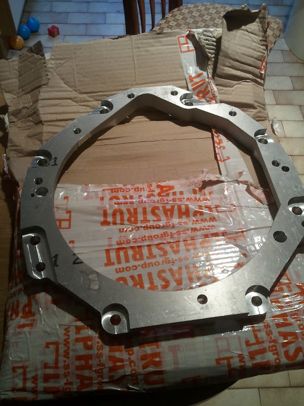
So despite the sub zero temperature in the garage I had to at least try out the adapter on the engine (the gearbox will have to wait until the snow has gone!)
So put it on and shock horror, it didn't fit.... it hit the flexplate/starter gear.
After a second of panic, thought "hmmm, is there a spacer", checked the manual and yep one spacer, so off with the flexplate, remove the spacer and try again. Now it fits (although I need a another dowel as one was missing).
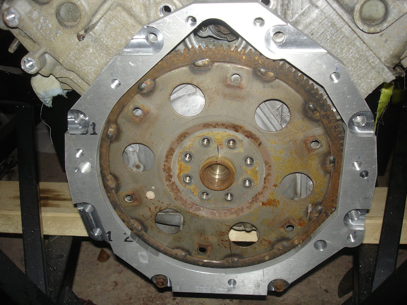
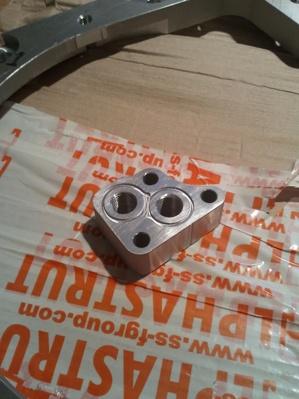
One advantage of water cutting, it does leave a nice finish!
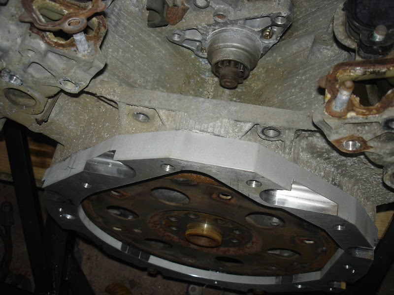
Just a shame the rest of the engine is (still) so manky. Still that's progressing.
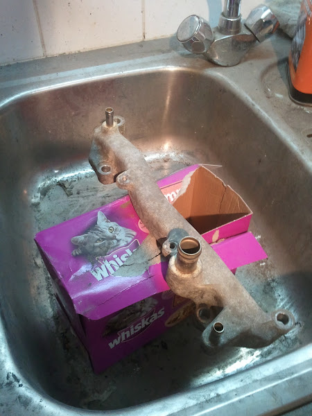
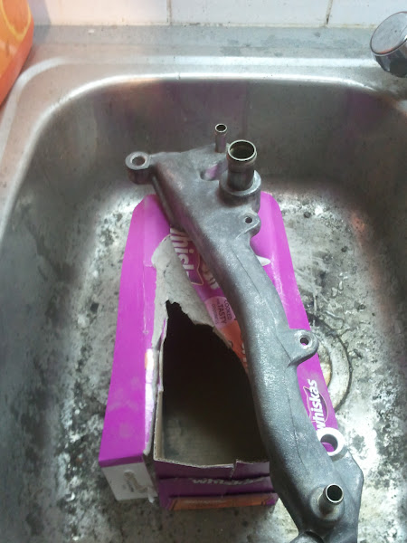

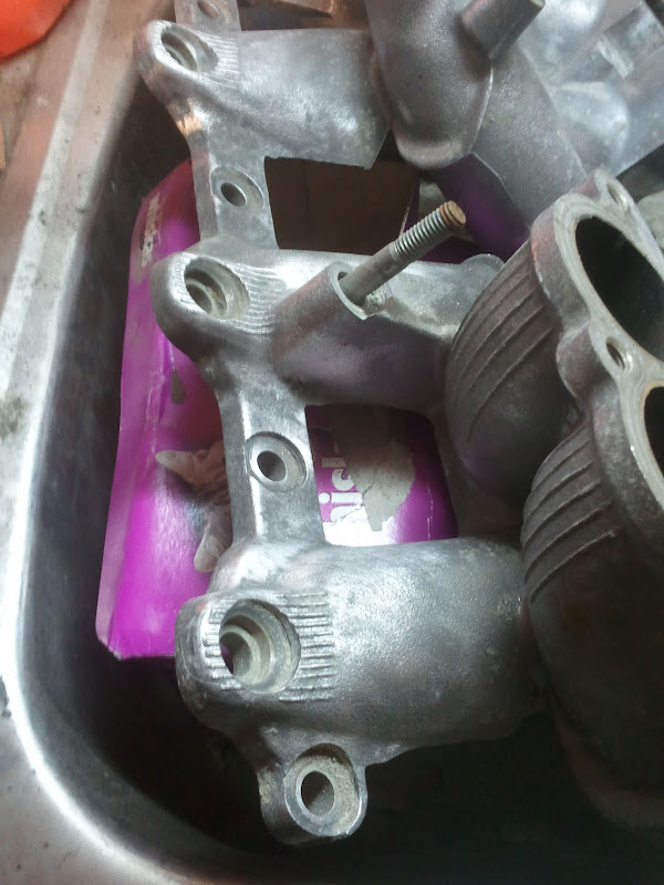
I've decided I'll paint the inlet manifold black (plus probably the bank to bank coolant 'tubes' as shown in the first two 'clean up' pictures) and polish up the fins on top.
Valve covers I think silver or polished as they're smooth rather than the rough sand cast finish of the inlet.
Block I haven't yet decided.
So despite the sub zero temperature in the garage I had to at least try out the adapter on the engine (the gearbox will have to wait until the snow has gone!)
So put it on and shock horror, it didn't fit.... it hit the flexplate/starter gear.
After a second of panic, thought "hmmm, is there a spacer", checked the manual and yep one spacer, so off with the flexplate, remove the spacer and try again. Now it fits (although I need a another dowel as one was missing).
One advantage of water cutting, it does leave a nice finish!
Just a shame the rest of the engine is (still) so manky. Still that's progressing.
I've decided I'll paint the inlet manifold black (plus probably the bank to bank coolant 'tubes' as shown in the first two 'clean up' pictures) and polish up the fins on top.
Valve covers I think silver or polished as they're smooth rather than the rough sand cast finish of the inlet.
Block I haven't yet decided.
It fits! epper: Trying not to look too surprised :thumbsup:
You may need to space the starter motor back so the it doesn't engage with the flex plate at rest (which mine did).
Oh and shave the heads down on the starter motor bolts which I think you've found out will foul already.
epper: Trying not to look too surprised :thumbsup:
You may need to space the starter motor back so the it doesn't engage with the flex plate at rest (which mine did).
Oh and shave the heads down on the starter motor bolts which I think you've found out will foul already.
:thumbsup:
I figured as much. I was actually going to ask if you had to spacer the starter back. Starter motor was off anyway so I hadn't considered bolt heads.
Still, have lathe, will modify.
Now all I need is to measure the bolt hole depths and get some bolts (I'm clean out of M12).
I know you used studs with nuts on the gearbox side, was there a reason? I'm tempted to just use cap screws.
The studs ensure you've max thread engagment without attempting to push the plate away from the engine.
Also I think at least one of the studs will foul the flexplate if screwed in too far
Lastly I think it helps allign the whole thing when assembling the unit.
The starter motor is as you know a PITA to get on and off, I wish I'd just thrown a new one on when I had then manifold off or at least I'd test it repeatedly before putting the manifold back on.
Semi thread hijack:Touche` --made in Orstralia mate:idea:
Say that's another one! I almost feel useful! Why's the flywheel different?
Im going to show my ignorance about engine suff now. But if your using a manual box, don't you need a fly wheel, not a flex plate? Or are you putting a flywheel on the flex plate?
flatchat(Chris)
Supporter
The easiest trans adaption is using the Porsche G50 / 930 or Ricardo style trans's -- where the starter is on the trans -- all the others are a PITA , so we use the motors original starter and ring gear (flex plate ) then bolton a custom flywheel to suit the clutch pak (290mm dia max)of your choice. This makes the adapter a bit thicker as well. In the end this set up is more user friendly as far as starting the bastard is concerned.
PS Doug -- different clutch on that one for a Swedish customer
:thumbsup:
PS Doug -- different clutch on that one for a Swedish customer
:thumbsup:
Normal life keeps intruding on building the car, however my wife finally got a 'sensible' car to replace the RX-8.

This means no more going to look at cars (hurrah), just need to sell the RX-8 now which will eat more time (and don't really want to sell it)
I have managed to do stuff on the car but nothing too exciting, mostly cleaning carbon out of the inlet manifold... I'm hating EGR at the moment.
Just about every night I've been cleaning the blasted thing. Grrrrr.
While I'm sure a few people won't be too surprised by this picture, although I risked frostbite to take it. Bloody cold, can't see me actually doing much in the garage until it warms up a bit.
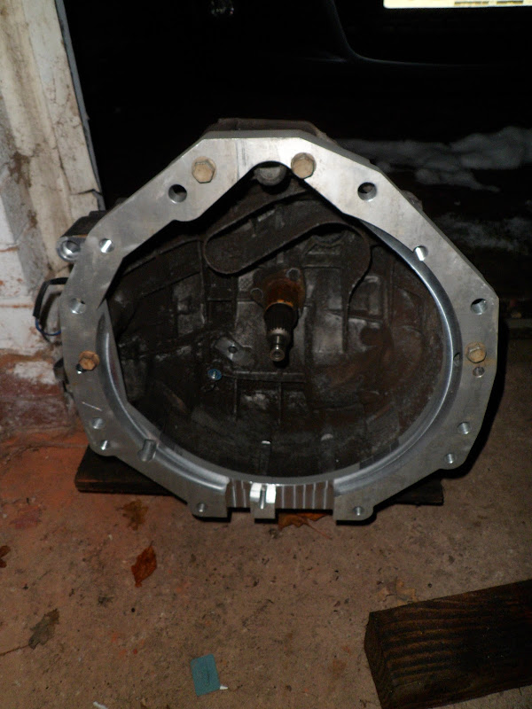
(yes I know the gearbox is still manky, I've just given it a quick wash but haven't started cleaning it properly yet).
This means no more going to look at cars (hurrah), just need to sell the RX-8 now which will eat more time (and don't really want to sell it
)I have managed to do stuff on the car but nothing too exciting, mostly cleaning carbon out of the inlet manifold... I'm hating EGR at the moment.
Just about every night I've been cleaning the blasted thing. Grrrrr.
While I'm sure a few people won't be too surprised by this picture
, although I risked frostbite to take it. Bloody cold, can't see me actually doing much in the garage until it warms up a bit.
(yes I know the gearbox is still manky, I've just given it a quick wash but haven't started cleaning it properly yet).
Mini update, spent the w/e fettling time on fitting a new starter to my daily runabout so nothing too exiting.
Ordered the bolts and studs I need to join engine to gearbox, should be able to trial fit them together this w/e. Second adapter plate is on ebay and have had enough offers to be happy it'll sell.
Still need the location dowels, once again hit the typical situation on the smaller 'cheap' parts, I need 3 dowels, about 50p each but postage makes it £8-10! Amazing how fast those kinds of costs rack up!
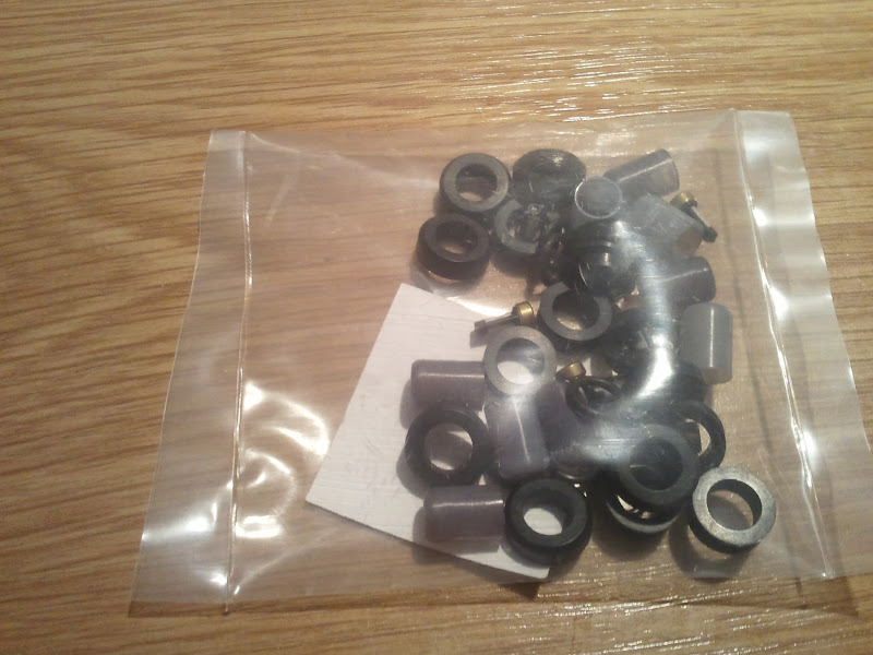
Got though the injector 'kit' from the US so have new pintle caps, micro filters and all the seals I need.
Rather annoyed with the £8 handling charge royal mail stuck on for the VAT though.
Mostly spent the last couple of weeks cleaning up the inlet manifold and tracts, bloody EGR! As its one of the items that is seen through the window want it to look smart, even if the rest of the engine was to look like a world war two engine I'd dug up... (it won't).
I also bought some paint for the inlet manifold but that stuck me with a dilemma, I was originally going to go for Halfords | Halfords Very High Temperature Paint Black 300ml with the ribs on top polished. When in Halfords however I spotted this Halfords | Halfords Very High Temperature Paint Metallic Black 300ml.
So now I'm not sure which one to go for. Bah. Comments or suggestions on which would look best welcome.
Ordered the bolts and studs I need to join engine to gearbox, should be able to trial fit them together this w/e. Second adapter plate is on ebay and have had enough offers to be happy it'll sell.
Still need the location dowels, once again hit the typical situation on the smaller 'cheap' parts, I need 3 dowels, about 50p each but postage makes it £8-10! Amazing how fast those kinds of costs rack up!
Got though the injector 'kit' from the US so have new pintle caps, micro filters and all the seals I need.
Rather annoyed with the £8 handling charge royal mail stuck on for the VAT though.
Mostly spent the last couple of weeks cleaning up the inlet manifold and tracts, bloody EGR! As its one of the items that is seen through the window want it to look smart, even if the rest of the engine was to look like a world war two engine I'd dug up... (it won't).
I also bought some paint for the inlet manifold but that stuck me with a dilemma, I was originally going to go for Halfords | Halfords Very High Temperature Paint Black 300ml with the ribs on top polished. When in Halfords however I spotted this Halfords | Halfords Very High Temperature Paint Metallic Black 300ml.
So now I'm not sure which one to go for. Bah.
Comments or suggestions on which would look best welcome.
Last edited:
Similar threads
- Replies
- 8
- Views
- 700
- Replies
- 24
- Views
- 3K