
Howard, great job! Amazing detail!

You are using an out of date browser. It may not display this or other websites correctly.
You should upgrade or use an alternative browser.
You should upgrade or use an alternative browser.
Howard B's RCR 40
- Thread starter hobrtl
- Start date
Fantastic progress! Have you given any thought to engraved panels to identify the dash switches. This place made panels for me at about $40 each
Aircraft Engravers - Engraving placards, vinyl lettering, data plates, fuel caps and rocker switches
Aircraft Engravers - Engraving placards, vinyl lettering, data plates, fuel caps and rocker switches
Guys,
Thanks for the great comments and encouragement.
Bill - I have friend with a Dymo from the 60's and just for fun I made my switch labels in Dymo tape. I did see the switch plates you had made. They are impressive. Maybe at alater time, it's on the B or C list for now.
Enjoy every day,
Thanks for the great comments and encouragement.
Bill - I have friend with a Dymo from the 60's and just for fun I made my switch labels in Dymo tape. I did see the switch plates you had made. They are impressive. Maybe at alater time, it's on the B or C list for now.
Enjoy every day,
Aircraft Engravers, their capabilities look good.
I have a 30" x 44" Laser with 100 watt of power and a powder coating system. We've done similar work where we laser etch the panel or plaque then clear powder coat. Etching is black and works well with SS, steel and brass. Aluminum absorbs the heat so the etching appears very light, but etching anodized aluminum looks great!
I have a 30" x 44" Laser with 100 watt of power and a powder coating system. We've done similar work where we laser etch the panel or plaque then clear powder coat. Etching is black and works well with SS, steel and brass. Aluminum absorbs the heat so the etching appears very light, but etching anodized aluminum looks great!
Mike,
Where are you in Virginia?
Where are you in Virginia?
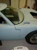
Here are the door and hinge mounting methods I used:
Tools:
Drill bits
Pencil
Dry erase marker
Electric variable speed hand drill
Caliper and measure-ometer (tape measure)
Belt sander and 80 grit belt
3m sanding block and 80 grit sand paper
Table saw
Drill press
Supplies:
Painters Tape
Weather strip
Scrap pieces of solid oak
Comments
I spent a lot of time “monkeying” with mounting the doors and hinges.
I finely hit on the right idea after several trials. I first tried with out weather strip in the doors. Then I tried again with weather strip in the door opening. The latter worked better for me.
This is just for mounting the doors and doesn’t include the door handle and latch hardware which I address later.
Procedure:
1. Properly secure and mount the rockers, front clip and spider first.
2. Trial fit the door in the opening with the weather strip in place.
3. Adjust the spider, rockers and front clip as close as you can.
4. Observe the door fits very tightly in the opening and rubs the spider in several places on the weather strip flange and at the edge of the door on the spider.
5. I began examining and marking the rubbing points and marking them with the pencil.
6. I then repetitiously began sanding and trial fitting the door(s) until all fit well in the opening of the spider also adjacent to the front clip with the weather strip in place.
7. I ignored the lower edge above the rocker until later. There was slight clearance, so it wasn’t a problem area. (RCR’s panels seem to be quite nice to work with for a novice working on fiberglass)
8. After numerous on again off again sanding and marking operations I was close and the doors fit in the opening relatively well.
9. I next mounted the hinges on the door per RCR instructions. It requires some tricky arm bending and working inside the door, but all in all not terribly difficult. I elongated the holes for adjustments later.
10. With the hinges mounted and in the closed position in the door opening I needed to measure the distance between the hinge and the mounting points on the “A” pillar in the car for roughing spacers. This was accomplished by first measuring the distance of the mounting surface of the hinge and the outside of the door while off the car. (I can’t remember the distance and can’t find where it is written, but it doesn’t matter.)
11. Using the thin wire rod on my micrometer I slipped it next to the door at the hinge point all the way to the “A” pillar for the second measure.
12. I subtracted the first measure from the second measure to get a rough spacer thickness.
13. I cut the scrap oak into spacers, set them in place on the hinges and secured them with a small screw to hold them in place through the extra hole in the hinge.
14. I marked the spacers for bolt holes, removed them and cut the holes on the drill press.
15. With the front clip removed I marked the mounting holes in the “A” pillar through the holes in the hinges and spacer mock ups.
16. I drilled the holes and mounted the door with out the bolts and the front clip in place.
17. I then systematically shaved off varying amounts of the wood shims/spacers with the belt Sander on auto-pilot. I did mark lines on the sides to keep from trimming to much.
18. After multiple bouts of step 17, I arrived at the right depths for the hinges. They are not squared they are shaped more in a wedge shape.
Time required: 12 hours or more (includes thinking time and frogging around to research the options on GT40s.com.)
Door and Door Hinge Mounting
Tools:
Drill bits
Pencil
Dry erase marker
Electric variable speed hand drill
Caliper and measure-ometer (tape measure)
Belt sander and 80 grit belt
3m sanding block and 80 grit sand paper
Table saw
Drill press
Supplies:
Painters Tape
Weather strip
Scrap pieces of solid oak
Comments
I spent a lot of time “monkeying” with mounting the doors and hinges.
I finely hit on the right idea after several trials. I first tried with out weather strip in the doors. Then I tried again with weather strip in the door opening. The latter worked better for me.
This is just for mounting the doors and doesn’t include the door handle and latch hardware which I address later.
Procedure:
1. Properly secure and mount the rockers, front clip and spider first.
2. Trial fit the door in the opening with the weather strip in place.
3. Adjust the spider, rockers and front clip as close as you can.
4. Observe the door fits very tightly in the opening and rubs the spider in several places on the weather strip flange and at the edge of the door on the spider.
5. I began examining and marking the rubbing points and marking them with the pencil.
6. I then repetitiously began sanding and trial fitting the door(s) until all fit well in the opening of the spider also adjacent to the front clip with the weather strip in place.
7. I ignored the lower edge above the rocker until later. There was slight clearance, so it wasn’t a problem area. (RCR’s panels seem to be quite nice to work with for a novice working on fiberglass)
8. After numerous on again off again sanding and marking operations I was close and the doors fit in the opening relatively well.
9. I next mounted the hinges on the door per RCR instructions. It requires some tricky arm bending and working inside the door, but all in all not terribly difficult. I elongated the holes for adjustments later.
10. With the hinges mounted and in the closed position in the door opening I needed to measure the distance between the hinge and the mounting points on the “A” pillar in the car for roughing spacers. This was accomplished by first measuring the distance of the mounting surface of the hinge and the outside of the door while off the car. (I can’t remember the distance and can’t find where it is written, but it doesn’t matter.)
11. Using the thin wire rod on my micrometer I slipped it next to the door at the hinge point all the way to the “A” pillar for the second measure.
12. I subtracted the first measure from the second measure to get a rough spacer thickness.
13. I cut the scrap oak into spacers, set them in place on the hinges and secured them with a small screw to hold them in place through the extra hole in the hinge.
14. I marked the spacers for bolt holes, removed them and cut the holes on the drill press.
15. With the front clip removed I marked the mounting holes in the “A” pillar through the holes in the hinges and spacer mock ups.
16. I drilled the holes and mounted the door with out the bolts and the front clip in place.
17. I then systematically shaved off varying amounts of the wood shims/spacers with the belt Sander on auto-pilot. I did mark lines on the sides to keep from trimming to much.
18. After multiple bouts of step 17, I arrived at the right depths for the hinges. They are not squared they are shaped more in a wedge shape.
Time required: 12 hours or more (includes thinking time and frogging around to research the options on GT40s.com.)
Attachments


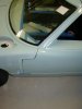
More hinge and door gap pics.
I plan on replacing the wood spacers with aluminum when I get to were I can do it nicely and with the appropriate shape.
I plan on replacing the wood spacers with aluminum when I get to were I can do it nicely and with the appropriate shape.
Attachments
Hi Rob,
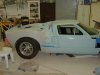
Thanks for the kind words, I am chipping away. I have been at it since June and have kept a log going with pictures and now I am just posting everything one bite at a time. I can't wait to get mine as half as nice as your build.
Here's more:
Tools:
Pencil (you always need one)
Electric variable speed hand drill
Electric grinder
File
80 grit sanding paper
Drill press
Various size drill bits.
Tape measure
Scissors
2 – ¾ Wrenches or wrench and socket with ratchet wrench
Allen wrench
Supplies:
Two ½ X 2 1/2 in. coarse thread bolts with washers and 2 regular nuts (as opposed to irregular nuts) and 2 nylok nuts)
8 - 3/8 in. x 1in. button hex head screws and nylok nuts
24 steel washers
Construction paper
Plate aluminum 3/8 in. thick, 13” X 36” scrap (approximately $30 from the local sheet metal suppliers, sheeze Louise they used to give scraps away when we were kids)
On this project I followed a modified “Chuck and Ryan” rear clip hinge construction. I felt a single hinge backing plate to support the weight of the clip on the hinge pins (bolts) should be more than adequate to alleviate wear and tear on the fiber glass clip mounting points if there is any. I used washers as spacers beneath the plate, which I will likely replace when I begin using fiber glass as Chuck and Ryan have done. I chose not to use inside plates to keep from adding unnecessary weight to the car. (I know, I have been reading too many race car magazines.)
Procedure:
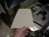
1. I first removed the clip and made hinge plate templates from construction paper
2. I went to the local sheet metal shop and purchased enough plate aluminum to do the job. They offered to cut the pieces but I wasn’t up for the added fees for doing the cuts.
3. The following week I was out at my friend Bill’s (a RF-40 builder practically from scratch and one heck of a nice guy) place and he told me his friend Randy could chop up my plates for me. 15 minutes later all for were done. I own Randy some favors.
4. Back at the ranch, I cleaned up the edges and sharp corners on the hinge plate with my grinder, file and heavy grit sanding paper.
5. I set up a mounting bolt pattern on the construction paper template, over laid it on the plates and cut holes in both plates on the drill press.
6. Then I measured out washer thicknesses to use as spacers under the hinge plates where Chuck and Ryan used wood and fiber glass.
7. I then placed the plates in the desired location on the clip and used it as a drilling template in the clip lower inner fender.
8. I completed this for both sides, then placed the washers behind the plates with washers also on the engine side of the inner fender and secured them with the ratcheting wrench and Allen wrench.
9. Using a motor cycle jack with a (blanket on it to minimize scratches) as a prop mechanism I set the clip standing on it’s tail on the jack and moved it into the open position behind the car.
10. I then pivoted the clip onto the chassis and realigned it with the spider and rocker panels.
11. I reached into the engine bay and set the small hinges in neutral position and tightened them securely with Allen wrench and ratcheting wrench.
12. Once I was comfortable with all the alignments (spider, rocker panels, rear clip, moon, stars, earth, sun…) I pulled out the big gun drill and punched holes through the hinge plates using the inner hinge hole as a guide and support.
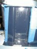
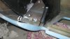
13. I set the 2 ½ in. bolts in from the inside of the wheel well with a washer, then on the other side I added the regular hex nut then another washer all the way onto the bolt then threaded the bolt through the inner hinge and secured it in place with the nylok nut, then moved the inside nut to pinch the hinge bolt to the inside hinge. (Okay, enough already, see the picture, it shows more with fewer words)
14. Side to side adjustments to the clip can be made by moving the bolts in and out without extra spacers. (Ala. Chuck and Ryan). Other adjustments back and forth, up and down are made with the inside hinge points and the trailing rods. As stated these were put in neutral positions for fine adjustment later.
Time required: 16 hours (includes thinking time, researching and getting parts, tools etc.) Frogging* around time 4 hours.
Total: 20 hours
* Frogging around – researching options old and new on GT40s.com and other internet places.
Frogging around time counts, it is part of the cognitive stages of “developing and doing”.
Thanks for the kind words, I am chipping away. I have been at it since June and have kept a log going with pictures and now I am just posting everything one bite at a time. I can't wait to get mine as half as nice as your build.
Here's more:
Rear Clip Hinges
Tools:
Pencil (you always need one)
Electric variable speed hand drill
Electric grinder
File
80 grit sanding paper
Drill press
Various size drill bits.
Tape measure
Scissors
2 – ¾ Wrenches or wrench and socket with ratchet wrench
Allen wrench
Supplies:
Two ½ X 2 1/2 in. coarse thread bolts with washers and 2 regular nuts (as opposed to irregular nuts) and 2 nylok nuts)
8 - 3/8 in. x 1in. button hex head screws and nylok nuts
24 steel washers
Construction paper
Plate aluminum 3/8 in. thick, 13” X 36” scrap (approximately $30 from the local sheet metal suppliers, sheeze Louise they used to give scraps away when we were kids)
On this project I followed a modified “Chuck and Ryan” rear clip hinge construction. I felt a single hinge backing plate to support the weight of the clip on the hinge pins (bolts) should be more than adequate to alleviate wear and tear on the fiber glass clip mounting points if there is any. I used washers as spacers beneath the plate, which I will likely replace when I begin using fiber glass as Chuck and Ryan have done. I chose not to use inside plates to keep from adding unnecessary weight to the car. (I know, I have been reading too many race car magazines.)
Procedure:
1. I first removed the clip and made hinge plate templates from construction paper
2. I went to the local sheet metal shop and purchased enough plate aluminum to do the job. They offered to cut the pieces but I wasn’t up for the added fees for doing the cuts.
3. The following week I was out at my friend Bill’s (a RF-40 builder practically from scratch and one heck of a nice guy) place and he told me his friend Randy could chop up my plates for me. 15 minutes later all for were done. I own Randy some favors.
4. Back at the ranch, I cleaned up the edges and sharp corners on the hinge plate with my grinder, file and heavy grit sanding paper.
5. I set up a mounting bolt pattern on the construction paper template, over laid it on the plates and cut holes in both plates on the drill press.
6. Then I measured out washer thicknesses to use as spacers under the hinge plates where Chuck and Ryan used wood and fiber glass.
7. I then placed the plates in the desired location on the clip and used it as a drilling template in the clip lower inner fender.
8. I completed this for both sides, then placed the washers behind the plates with washers also on the engine side of the inner fender and secured them with the ratcheting wrench and Allen wrench.
9. Using a motor cycle jack with a (blanket on it to minimize scratches) as a prop mechanism I set the clip standing on it’s tail on the jack and moved it into the open position behind the car.
10. I then pivoted the clip onto the chassis and realigned it with the spider and rocker panels.
11. I reached into the engine bay and set the small hinges in neutral position and tightened them securely with Allen wrench and ratcheting wrench.
12. Once I was comfortable with all the alignments (spider, rocker panels, rear clip, moon, stars, earth, sun…) I pulled out the big gun drill and punched holes through the hinge plates using the inner hinge hole as a guide and support.
13. I set the 2 ½ in. bolts in from the inside of the wheel well with a washer, then on the other side I added the regular hex nut then another washer all the way onto the bolt then threaded the bolt through the inner hinge and secured it in place with the nylok nut, then moved the inside nut to pinch the hinge bolt to the inside hinge. (Okay, enough already, see the picture, it shows more with fewer words)
14. Side to side adjustments to the clip can be made by moving the bolts in and out without extra spacers. (Ala. Chuck and Ryan). Other adjustments back and forth, up and down are made with the inside hinge points and the trailing rods. As stated these were put in neutral positions for fine adjustment later.
Time required: 16 hours (includes thinking time, researching and getting parts, tools etc.) Frogging* around time 4 hours.
Total: 20 hours
* Frogging around – researching options old and new on GT40s.com and other internet places.
Frogging around time counts, it is part of the cognitive stages of “developing and doing”.
Attachments
I modified the first installation of the rear clip hinges as described below.
Tools:
Pencil (you always need one)
Electric variable speed hand drill
Electric grinder
File
80 grit sanding paper
Drill press
Various size drill bits.
Tape measure
Scissors
2 – ¾ Wrenches or wrench and socket with ratchet wrench
Allen wrench
Supplies:
Two ½ X 2 1/2 in. coarse thread bolts with washers and 2 regular nuts (as opposed to irregular nuts) and 2 nylok nuts)
8 - 3/8 in. x 1in. button hex head screws and nylok nuts
24 steel washers
Construction paper
Plate aluminum 3/8 in. thick, 13” X 36” scrap (approximately $30 from the local sheet metal suppliers, sheeze Louise they used to give scraps away when we were kids)
Comments:
On this project I un-modified “Chuck and Ryan’s” rear clip hinge construction. I decided I needed something else to do and went to a double hinge plate set-up to support the weight of the rear clip on the hinge pins bolts. I used washers as spacers beneath the plate, which I will likely replace when I begin using fiber glass as Chuck and Ryan have done. I chose to add the inside plates.
Procedure:
1.I first removed the clip and made hinge plate templates from construction paper
2.I had purchased enough plate aluminum to finish the job.
3.I followed the same procedure as the other hinge plates on the outside of the inner fender well.
4.I cleaned up the edges and sharp corners on the hinge plates with my belt sander mounted in the work-mate.
5.I set up mounting bolt patterns by laying the same side plates together marking through the outside plates already constructed. I made sure the new plates would align correctly in the recessed area of the fender well. I then overlaid the plates correctly and cut holes on the drill press through the existing holes from the inside mounts.
6.The plates were test fitted to the inner fender wells, then mounted back on clip.
7.The clip was mounted back on the car.
Time required: 6 hours
Rear Clip Hinges Part II
Tools:
Pencil (you always need one)
Electric variable speed hand drill
Electric grinder
File
80 grit sanding paper
Drill press
Various size drill bits.
Tape measure
Scissors
2 – ¾ Wrenches or wrench and socket with ratchet wrench
Allen wrench
Supplies:
Two ½ X 2 1/2 in. coarse thread bolts with washers and 2 regular nuts (as opposed to irregular nuts) and 2 nylok nuts)
8 - 3/8 in. x 1in. button hex head screws and nylok nuts
24 steel washers
Construction paper
Plate aluminum 3/8 in. thick, 13” X 36” scrap (approximately $30 from the local sheet metal suppliers, sheeze Louise they used to give scraps away when we were kids)
Comments:
On this project I un-modified “Chuck and Ryan’s” rear clip hinge construction. I decided I needed something else to do and went to a double hinge plate set-up to support the weight of the rear clip on the hinge pins bolts. I used washers as spacers beneath the plate, which I will likely replace when I begin using fiber glass as Chuck and Ryan have done. I chose to add the inside plates.
Procedure:
1.I first removed the clip and made hinge plate templates from construction paper
2.I had purchased enough plate aluminum to finish the job.
3.I followed the same procedure as the other hinge plates on the outside of the inner fender well.
4.I cleaned up the edges and sharp corners on the hinge plates with my belt sander mounted in the work-mate.
5.I set up mounting bolt patterns by laying the same side plates together marking through the outside plates already constructed. I made sure the new plates would align correctly in the recessed area of the fender well. I then overlaid the plates correctly and cut holes on the drill press through the existing holes from the inside mounts.
6.The plates were test fitted to the inner fender wells, then mounted back on clip.
7.The clip was mounted back on the car.
Time required: 6 hours
Attachments
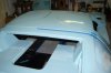
One more before I get back in the salt mine!
Tools:
2½ in. hole saw (Home Depot – Rigid)
Hand held hack saw
1½ in. sanding drum
Pencil
Electric variable speed hand drill
Supplies:
Headlamp template made from construction paper
Head lamps (from RCR)
Procedure:
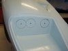
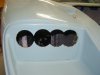
1.I lined the bottom of the template 1/8 in. from the bottom of the lamp opening location on the right side of the clip.
2.Then traced out the template onto the opening location, centered between the sides wall forward of the lamp.
3.The 2 ½ in. hole saw was use to take out as much material as possible. I don’t have a saw that I can operate with my hand so close to the forward walls forward of the head lamp opening. I try to cut close but not over the markings of the template.
4.I then use the hand hacksaw to get it close to the lines as possible. This was the time consuming part of the job, boring not hard.
5.The drum sander was used to finish off the edges. It is still a little rough and I got caught in a tiny cavity on the left side opening and took out a tad too much in one spot, not pretty, but it’s repairable at fill time.
6.I didn’t have the ability to print out the head lamp mount plate template or the aluminum to cut into. I am saving that for a later project. I am also trying to rethink the head lamp mounting to be easier. I report it if I figure it out.
Time required: 4 1/2 hours (includes thinking time and getting parts).
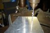
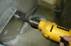
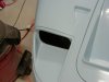
Head Lamp Cut-outs
Tools:
2½ in. hole saw (Home Depot – Rigid)
Hand held hack saw
1½ in. sanding drum
Pencil
Electric variable speed hand drill
Supplies:
Headlamp template made from construction paper
Head lamps (from RCR)
Procedure:
1.I lined the bottom of the template 1/8 in. from the bottom of the lamp opening location on the right side of the clip.
2.Then traced out the template onto the opening location, centered between the sides wall forward of the lamp.
3.The 2 ½ in. hole saw was use to take out as much material as possible. I don’t have a saw that I can operate with my hand so close to the forward walls forward of the head lamp opening. I try to cut close but not over the markings of the template.
4.I then use the hand hacksaw to get it close to the lines as possible. This was the time consuming part of the job, boring not hard.
5.The drum sander was used to finish off the edges. It is still a little rough and I got caught in a tiny cavity on the left side opening and took out a tad too much in one spot, not pretty, but it’s repairable at fill time.
6.I didn’t have the ability to print out the head lamp mount plate template or the aluminum to cut into. I am saving that for a later project. I am also trying to rethink the head lamp mounting to be easier. I report it if I figure it out.
Time required: 4 1/2 hours (includes thinking time and getting parts).
Attachments
Nice work Howard! :thumbsup:
I'm curious about the spacer widths that you're going to need to get the hinges to align to the mounts on the rear tray...
When I have the rear tray mounts moved all the way to the edge on both sides, I have one spacer that's about an inch and the other only about 1/4"..
I have trimmed my rear clip to be square to the spider and spider to the chassis etc..
I'm not so sure that my rear tray is square to the chassis right now - I would have to re-measure it.
Randy,
I am not sure I understand your question. What I didn't mention was that I am not using any spacers. I was thinking of a "better way" to adjust the rear clip.
Here is what I did, I created a hinge with out spacers by using a long threaded bolt in the hinge on both sides, I used nylocks to pinch both the clip and the hinge mounting point. There is enough thread to move the clip right and left to where it is centered. I will check to see if I have some pictures and post them for you.
Cheers
randy,
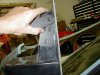
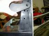
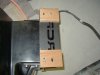
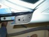
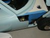
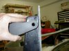
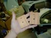
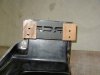
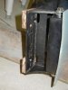
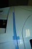
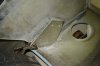
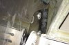
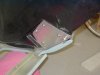
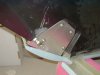
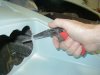
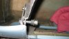
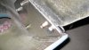
I did not have any pictures so I just went out and took some. I can't demo it because the clip is off the car. The clip rides on the flat part of the bolt (I have some grade 8 replacements for these). As you can see the head of the bolt will be on the wheel well side. The wheel well wall rides free on the bolt but is flush against the bolt head and its washer. The inside nylock (regular nut in the picture) and washer pinches the tray mounting point with the other nylock on the inside. No measured washers are required and it allows wiggle room for adjustment.
That's the best I can describe it. Does something look wrong with this arrangement that I may be overlooking?
Thanks for any hints...
Attachments
randy,
I did not have any pictures so I just went out and took some. I can't demo it because the clip is off the car. The clip rides on the flat part of the bolt (I have some grade 8 replacements for these). As you can see the head of the bolt will be on the wheel well side. The wheel well wall rides free on the bolt but is flush against the bolt head and its washer. The inside nylock (regular nut in the picture) and washer pinches the tray mounting point with the other nylock on the inside. No measured washers are required and it allows wiggle room for adjustment.
That's the best I can describe it. Does something look wrong with this arrangement that I may be overlooking?
Thanks for any hints...
Hi Howard,
Okay - I see what you're doing now.. I don't really see anything wrong - but that might be a bunch of weight to be hanging on those bolts if there's not a spacer of some sort to help transfer the load to the brackets. I know that your brackets are very stout on the body, but the brackets on the tray are not that stout and I think may need those spacers...
I could be wrong and still not understanding your approach.. I liked the solution that Eglitom used and am hoping to do something along the same line myself. If I can ever get back out to the shop that is.. ((sigh))
Tom,
I didn't get hinge plates, they may have come with later cars, so I made mine.
Randy,
You may be correct. I will look at Tom's set up. The way I see it most of the clip weight is moved to the chassis once the clip is close and buttoned up. I am not an engineer so I need help on this stuff, that is why I got grade 8 replacement bolts. The weight and stress distribution to the clip is spread over the four plates and not on the fiberglass. The weight to the tray when closed seems to be negated since it's a down force, just as if it were laying on the ground. The inside hinge point on the tray just serves to keep it in place. I need someone smarter than me to know if I have faulty logic here.
Randy:
I really don't think the spacers (washers) add any significant support. The brackets seem to be plenty strong to support the clip as Howard has done it. Howard's approach makes adjustment a whole lot easier. Trying to fiddle with a stack of washers to accomplish a small lateral adjustment is a real pain.
Mine has been in place now for many months, seems I am opening and closing it almost daily, and it remains solid and secure.
Regarding the descrepancy in the spacing of the brackets, left to right, I had the same situation. Once the rear clip was lined up with various reference points, including the spider, tires, etc., there was about a 3/4" or so descrepancy in the location of the hinge brackets, left to right. I suspect it has more to do with the way the fiberglass liner is secured to the fiberglass shell. In any event, there was enough adjustment in the bracket that it really did not matter.
Of course the ultimate way to mount the rear clip is Tom (Eglitom)'s approach.
Similar threads
- Replies
- 24
- Views
- 3K
- Replies
- 2
- Views
- 358
- Replies
- 3
- Views
- 525