Howard B's RCR 40

I just read Tom's post again using the bobbins. That is very nice. I noted it back when he posted. This is pushing me to think harder about the mounting of the clip and hinge points. I will put it in my knowledge bin and get back to it later when I can over my technical shortcomings.

BTW who sells the bobbins?

Randy, I read my last post to you and realized the last sentence could be read several ways! :laugh::laugh: I meant it more like I am closer to Forrest Gump when he said, "I'm not a smart man" and need all the advice I can get.

That's what make GT40s.com such a great place to hang out and learn.

Chuck, between you and Tom and ten others I should arrive at my destination.

Cheers to you all,
 
I shortened my lugs to the recommended length the old fashion way.
Hint: Use a sharp saw!
 

Attachments

  • Stud shortening event 1.jpg
    Stud shortening event 1.jpg
    170.2 KB · Views: 618
  • Stud shortening event 2.jpg
    Stud shortening event 2.jpg
    135.6 KB · Views: 552

Randy V

Moderator-Admin
Staff member
Admin
Lifetime Supporter
I've no issues with your response Howard - It's all good... I agree that using stacks of washers are simply not the correct answer..

I take it that you've discovered that one Bobbin needs to be longer than the other. I'm only using spacers behind one Bobbin and have cut down the opposite for now as a temporary measure while I reengineer the front clip to be a tilt unit like the rear clip.

You have different lug studs than I had on my car in that yours are longer and have shoulder. Mine only needed about 1/4" cut off. To do that I make use of my Wiz-Wheel. You can buy them quite inexpensively and they come in handy on Sooooo many projects.

Craftsman Cut Off Tool - 19953 at Sears.com

00919953000
 
Randy,
I broke down and coughed up a couple of nickles and bought a cut off wheel after I had done this job. Life gets better everyday.

I am now practicing rear wheel alignment techniques posted by both Tom (Eglitom) and Kieth W. in Alabama. Two great posts.

I see you had your paw prints in their posts. Good stuff :thumbsup:

Howard
 
Howard

here is the drawing you asked for. Actualy it is a sketch i have done the last 5 minutes, not nice but showing the main dimension of the rear frame.

I haven´t done any drawing for mine, i took the RCR rear pan and the rear clip ( distance between the two hinge cutouts) dimensions as a base for the frame.
After finishing the rear frame with the slider plates i made the "horseshoe" plates and spaced them, that they are centered in the hinge cutout.
THan i put my rear clip on, supported by the wooden bars you can see on my built log in the body aligning part and aligned it to the final postion left to right, front to aft and heightwise.
After doing so i was able to define the exact dimension of the bobbins. I made the bobbins in my lathe and mounted everything. Finally i was off 3mm to the left side, so i shortened the left bobbin by 1,5mm and put a washer underneath the right one.
The final bobbins will be made of black PU according to the corrected dimensions.

I can take of and put on the rear clip without any help. i just put a carpet on the backside of the car and open the rear clip until the spoiler touches the floor. THan using this point as a hinge point i crank the rear clip back even further and the horseshoes slide of the bobbins nicely and enables me to lift the rear clip away. Putting it on is the same action just reversed. One minute on and off is no problem.
Actually by thinking about it, as i have never put an vid to youtube, this is one i could make.
originalstylerearframesketch.jpg

TOM
 
Last edited:

Randy V

Moderator-Admin
Staff member
Admin
Lifetime Supporter
Fabulous.. Just great!!! I have printed the frame mod and watched the video.. I need to go back to your build thread and find the info about your horseshoes for the mounts..
 
Tom,

Awesome, you teach me one minute, it's in a video the next for everyone to see. That is a clean set-up.

Randy, if you haven't found it, it is on page three of Tom's build.

Thanks Tom.
 
Switch Mounting


Tools:
Cone shaped drill bit
Small drill bit
Metal punch
Drill press
Small round file
Pencil
Marker pen
Painter’s masking tape (2 inch)
Caliper and tape measure
Large jaw Vise-grip panel clamp
Block of wood
Straight edge

Supplies:

Set of Lucas style switches (from Finishline as in Chuck and Ryan’s post)
Aluminum switch plates (already shaped and fitted earlier)
Dymo tape labeler (yeah, from the 60’s)

Procedure:

1. I sat in the car to figure out where to strategically place the switches.
2. I measured out where the outer edges of the steering wheel are on each side of the steering column for ease of access to switches with my hands on the wheel in the driving position. (I strayed from replicating any original cars for my own safety.)
3. I covered the switch plate centers length ways with the blue painters tape. (for marking and remarking)
4. After measuring the diameters of the switches I marked the hole sizes in the plates.
5. I drilled starter holes on the drill press, then using the conical drill bit I cut the appropriate size holes for each switch.
6. After mounting the switches I got the Dymo out and made some tape labels just like in the race cars. It’s a cute touch that I will probably replace later.
7. The pictures tell the story.

Time required: 4 hours
 

Attachments

  • Switch plates 001.jpg
    Switch plates 001.jpg
    146.5 KB · Views: 408
  • Switch plates 002.jpg
    Switch plates 002.jpg
    141.1 KB · Views: 383
  • Switch plates 003.jpg
    Switch plates 003.jpg
    110.7 KB · Views: 384
  • Switch plates 004.jpg
    Switch plates 004.jpg
    76.5 KB · Views: 427
  • Switch plates 005.jpg
    Switch plates 005.jpg
    111.7 KB · Views: 444
More pics of the switch panels...
 

Attachments

  • Switch plates 006.jpg
    Switch plates 006.jpg
    136.3 KB · Views: 463
  • Switch plates 007.jpg
    Switch plates 007.jpg
    127.3 KB · Views: 614
  • Switch plates 008.jpg
    Switch plates 008.jpg
    115.4 KB · Views: 458
  • Switch plates 009.jpg
    Switch plates 009.jpg
    120.9 KB · Views: 574
  • Switch plates 010.jpg
    Switch plates 010.jpg
    134.8 KB · Views: 557

Chuck

Supporter
Howard:

Man, you are BLASTING through this project! It sure is looking good. I like you concise and well illustrated explanations, and I am sure a lot of others starting an RCR will likewise.

Chuck
 
Chuck,

I am not intentionally trying to create an illusion of speed. I realize that may be happening. I began my build the day after I returned from Fran's RCR facility in June of last year. I have worked on it continuously since that time. I truly have documented every thing to honor all you other guys who have been diligently carrying the rest of us RCR builders through the hard parts of building. I do truly enjoy working on this car and want to be a "good" contributor to the build logs on GT40s.com. I feel I need to carry my share for all the help I have received through reading the other builds going on (RCR or others).

I am a rookie and a novice, but I am a car guy! 99% of the guys you run into on this site are a great bunch of guys, always stepping up to help each other out. I want to be in that crowd as well!

I am attempting to stretch my skill sets to do something I truly enjoy and also brings with it friendships along the way. That seems to be occuring naturally.

I have even used the occasion to venture into writing and have written a short story of the couple of days I spent picking up my car. It is a comedy, I am certain others will be able to relate with. I am going to share it eventually when I feel comfortable with the ending. Writing is not my strong suite, so I have been attempting to stretch myself there as well.

I have about thirty or so more posts of tasks I have completed and documented in word files and pictures. New guys should be able to copy them off into word documents, combine them with great documentation from other builders and build their own personal shop manuals. I am sure this would cut down on "how do you do this....?" phone calls to Fran (and other manufacturers) so he and they can focus on building the coolest cars! :thumbsup::thumbsup::thumbsup:

BTW, as far as I can tell I have chassis # 40, I think that is a nice coincidence.

All the best, thanks for all the help you didn't know you were giving me these past couple of years.
 
Hi Molleur,
You are a friend of my friend Will, true? Well nice to meet you.
Thanks for your kind words.
Here's my next installment.

Door Handle Mounting


Tools:
½ in. drill bit
Jig saw
½ in. sanding drum
Pencil
Dry erase marker
Electric variable speed hand drill
Quick lock flexible shaft drill extension ($9, Sears Craftsman off the shelf)
Quick lock drill bits 13/64 and 3/8 (Sears Craftsman, small one on sale $2 and $3.99 for the 3/8 in.)
Standard rasp file flat on one side round on the other
Quick lock counter sink bits (also Sears Craftsman, $5 for four)
Measure-ometer.

Comments:
I followed instructions in the RCR manual and checked out other sites. I will probably revisit the door handles and mechanisms after I have completed the build. I did try to keep it really simple.

Supplies:
Two 3/8 X 2 in. clevis pins ($1.80 ea.) at the local hardware store
Two clevis pin clips (22 cents a piece)
One ½ od X ½ in. nylon washers, with a 3/8 inch id.
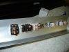
Door handles (from RCR)

Procedure:

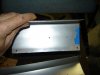
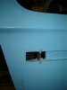
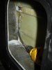
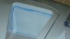
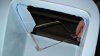
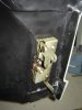
1. Cut the handle hole. Start with the ½ in. drill bit and take out as much material as possible. Similar to all other instructions.
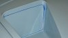
2. Use the jig saw to cut out the sides of the hole and fashion corners in the hole.
3. Use the small drum sander and file to widen the hole to allow the handle to fit and swing easily. File out the corners square.
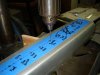
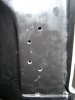
4. Mark the center line on pivot hole on both sides of the handle with the dry erase marker.
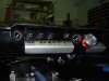
5. Set the handle in the door to the approximate final location.
6. Mark the door with the pencil to match the center lines on the handle, one mark on the top and bottom each.
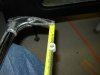
7. Measure the distance from the center of the holes in the handle and where the handle aligns with the edge of the handle recess in the door.
8. Measure and mark that distance in the inside of handle recess in the door from the pencil marks you made in the door.
9. Mark and “X” with the crossing point where you marked the center of the hole.
10. Draw the line all the way to the back of the handle hole inside the door.
11. Measure the distance from the middle of the “X” to the back of the handle hole.
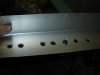
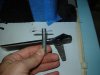
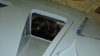
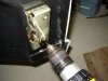
12. Using the flexible quick lock driver shaft and counter sink drill bit to start the hole for the handle pin, place the drill inside the door and drill from the bottom up. There isn’t enough space to drill from the top side.
13. From inside as closely as you can move the counter sink bit the distance you measured to start the hole.
14. Drill upwards with the small bit and hopefully you will come out at the center of the “X”. You should not start to counter sink the hole if you are off. If you are off, move the bit and drill again. The small bit allows for some error. When you hit the mark press the drill further in to counter sink the hole and center your starting point for the next larger bits. This allows you to miss and recover. The difference between a good carpenter and a bad one is the good one recovers nicely from mistakes.
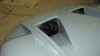
15. Next you use the longer narrow bit to enlarge the hole, starting in the counter sunk hole. Drill slowly so the action doesn’t get away from you. When you have completed the lower hole, do not remove the bit from the hole. You carefully set the point of the stopped bit at the center of the upper hole, then squeeze the trigger and continue slowly upwards to start the opening of the upper hole. I had to press the flexible shaft hard to the inside of the door to keep it centered and true to start the second hole.
16. Repeat step 15 increasing the bit size all the way to 3/8 in.
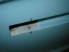
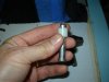
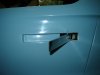
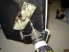
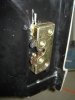
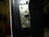
17. Test fit the handle to the door using the clevis pin as the pivot for the handle.
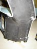
18. To keep friction off the fiber glass above and below where the clevis pin enters and exists the door I measured the distance between the bottom of the fiber glass below the handle and where the clip fits in the clevis pin. The pin was in without any washer(s) and laying flat at the top. I divided the distance by 2 (1/5 in./2) and cut two nylon washers 1/10 in. each.
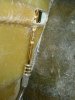
19. I placed one washer at the top of the clevis pin above the fiber glass and the other below between the bottom of the fiber glass and clip. I then inserted the clip. Minor sanding was required inside the door for the second washer to fit.
20. Repeat for the other door.

Time required: 5 hours for the first one (includes thinking time and getting parts) and 2 1/2 hours for the second one. Frogging around time 3 hour.
Total: 10 ½ hours
 

Attachments

  • Door Handle 001.jpg
    Door Handle 001.jpg
    83.5 KB · Views: 436
  • Door Handle 002.jpg
    Door Handle 002.jpg
    210.9 KB · Views: 491
  • Door Handle 003.jpg
    Door Handle 003.jpg
    32.9 KB · Views: 478
  • Door Handle 004.jpg
    Door Handle 004.jpg
    10.1 KB · Views: 460
  • Door Handle 005.jpg
    Door Handle 005.jpg
    116.3 KB · Views: 512
I have some rubber bumpers I pick up at the Fall Carlisle meet to install to make the handles parallel to the door surface and a cleaner look in the door.

A few more pics for the visual learners amongst us...
 
Ooops, I'll try again...
 

Attachments

  • Door Handle 006.jpg
    Door Handle 006.jpg
    111.4 KB · Views: 469
  • Door Handle 007.jpg
    Door Handle 007.jpg
    134.7 KB · Views: 429
  • Door Handle 008.jpg
    Door Handle 008.jpg
    21.1 KB · Views: 485
  • Door Handle 009.jpg
    Door Handle 009.jpg
    83.5 KB · Views: 465
Tonight's dinner offering...

Double Nostril Hood Cut Out


Tools:
Variable speed drill
2 inch hole saw
Coping saw
Drum sander
Sanding block
Tape measure
Straight edge
Water soluble marker

Comments:

This was a straight forward task which I felt was worth commenting on because the coping saw worked more easily than electric tools and made less of a dust mess.

I monkeyed around with power tools then hit upon using the coping saw.

Procedure:
1. Mark out the cut outs with the marker, tape measure and straight edge.
2. Make starter holes with the 2 inch hole saw and drill.
3. Use the coping saw by detaching it and assembling it with the blade inside the hole cut out and the saw frame outside of the panel to start.
4. Cut along the top edge and down the sides first.
5. Then twisting the blade into various positions cut out ever larger pieces of fiberglass.
6. Eventually you can disassemble the saw and cut from inside the opening. The saw, with a fresh blade cuts incredibly fast with good control.
7. Finish sand the edges to your liking.

Time: 4 ½ hours.
 

Attachments

  • Front lid nostrils 004.jpg
    Front lid nostrils 004.jpg
    75.6 KB · Views: 383
  • Front lid nostrils 005.jpg
    Front lid nostrils 005.jpg
    69.4 KB · Views: 379
  • Front lid nostrils 006.jpg
    Front lid nostrils 006.jpg
    80.9 KB · Views: 446
  • Front lid nostrils 012.jpg
    Front lid nostrils 012.jpg
    81.9 KB · Views: 421
  • Front lid nostrils 013.jpg
    Front lid nostrils 013.jpg
    79.4 KB · Views: 447
Desert...

Door Latch Mounting
Tools:
¼ and 3/8 in. drill bits
Jig saw
1 ½ inch cutting disc
Pencil
Dry erase marker
Electric variable speed hand drill
Caliper and measure-ometer (tape measure)
Allen wrench
Small lamp

Supplies:
Two Bear Claw door latches (from RCR)


This does not cover the latch catch bolts. I am still thinking about how best to mount them nicely.

I researched how others had mounted the latches (slim pickins’), in the door versus external on the door. Ron McCall showed his internal set up, with a slightly different latch set-up and release lever then mine. If I mount them internally the catch bolt mounted on the fire wall needs to extend about 3 inches out (not very pretty) and about 2 inches if the latch is on the outside of the door. I chose to mount the latches externally because everyone knows size does matter, and I could picture myself or a passenger getting grabbed more frequently on the longer peg position. If I figure out or see a better solution for the internal mount I will switch over later. The attaching holes are in the same position. I would need to cut out the opening for the claws and fill the slots made for the release levers.

The latch comes with an up and down locking arm which I removed for the external application. If the latch makes it back inside the door I will use them then.

Procedure:

1. Measure the location of the door latches on the side of the door and check for clearance by measuring gaps when the door is closed. This was done from inside the car with the door closed.
2. Since the left door latch mechanism is the reverse (mirror image) of the right I used it as a drilling template for the right side by flipping it over and drilling through the bolt holes into the right side door. I used the smaller bit to start a pilot hole and to avoid erasing the threads in the bolt holes of the latch.
3. I then secure the mechanism in place by moving the latch out of the way, completed the widening of the hole to the proper size (plus wiggle room) with the larger bit, put the latch back in place and secured it from the inside with a screw and Allen wrench.
4. I then drilled pilot holes through the other bolt holes into the door.
5. Removed the latch again, drilled the remaining holes to the proper size and did a check fit with the same latch template. (Left one upside down)
6. I located and market on the door where a slot had to be cut for the release lever to go into the door. A wide spot opening needs to be made for the lever and it’s pivot pin on the latch.
7. I figured the lever insert hole would be close to one of the bolt holes I had just drilled and weaken the fiber glass near the hole. I determined it would be better to cut the lever (which is “T” shaped) insert hole higher up and widen the opening at the bottom to allow the lever room to move freely and the “T” lever would hang inside the bottom of the slot. (The picture is probably easier to understand then my words!) It worked out.
8. I cut the first door slot with the jig saw and drilled starting holes. The second door (left side) I used the cutting disc on the VS Drill to maintain control of the cut. I managed to nick the door anyway, but should easily repair.
9. The latch release lever has a very short throw. Since I need an attachment link to the door handle, a direct link would pop the latch open before the handle is all the way out to a comfortable opening position. I need to create a link that allows the door latch to pop open when the handle is further out of the door. I am still working on this solution, possible a wire cable, but I want it to be quiet and not rattle when the door is closed.
10. The left door install is in the same manner, with the right door latch as a drilling template. I use the cutting wheel more effectively than the jig saw.

Time required: 5 hours (includes thinking time and frogging around to research the options on GT40s.com.)
Total: 5 hours (Sometimes I think too much, some times I don’t think enough!)
 

Attachments

  • Door Locks 1.jpg
    Door Locks 1.jpg
    20.3 KB · Views: 438
  • Door Locks 2.jpg
    Door Locks 2.jpg
    21 KB · Views: 485
  • Door Locks 3.jpg
    Door Locks 3.jpg
    134.5 KB · Views: 449
  • Door Locks 4.jpg
    Door Locks 4.jpg
    131.8 KB · Views: 432
  • Door Locks 5.jpg
    Door Locks 5.jpg
    19.5 KB · Views: 406
Back
Top