Good work Jim..
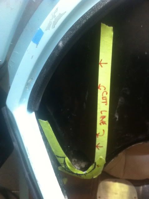
Make sure you get some sort of support up to that spider to keep it elevated otherwise the windshield will not fit and your door alignment will change.
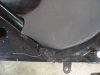
I made a support brace system coming from the top of my roll cage to the spider both front and rear which will make the spider 100% more stable and repeatable alignment even with removing and reinstalling the spider a dozen times.
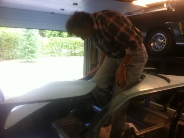
Here are a few pics for you that I have not put up on my website yet just in case you are curious
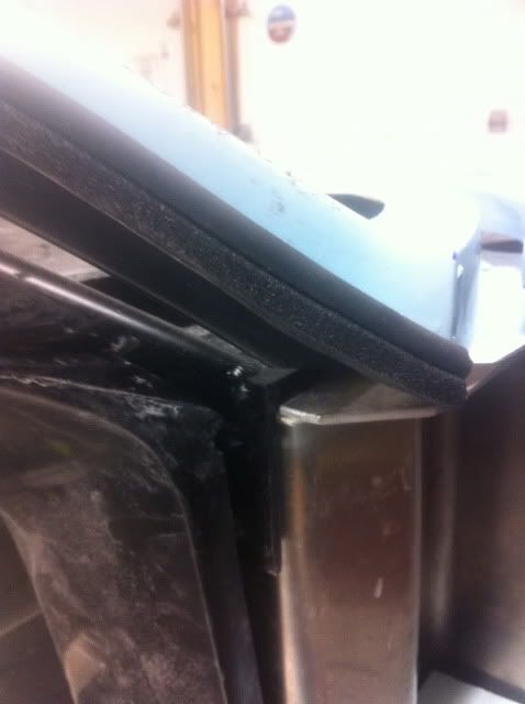
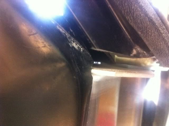
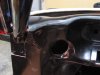
This is looking up at the center of the spider at the top of the windshield.


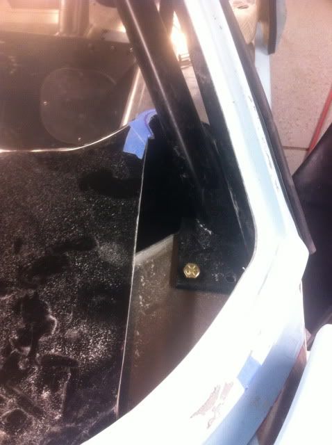
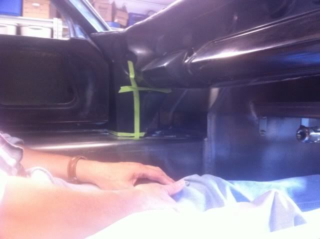
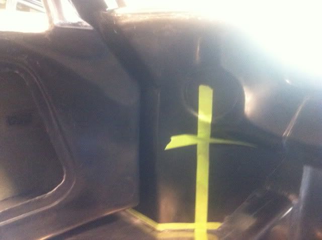
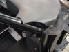
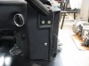
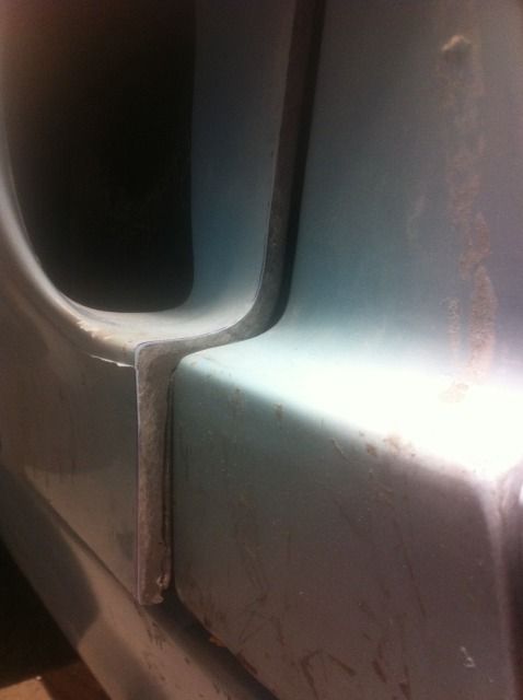
I put side supports on the top of the cage front and rear and drilled, screwed into the spider here.

Make sure you get some sort of support up to that spider to keep it elevated otherwise the windshield will not fit and your door alignment will change.
I made a support brace system coming from the top of my roll cage to the spider both front and rear which will make the spider 100% more stable and repeatable alignment even with removing and reinstalling the spider a dozen times.
Here are a few pics for you that I have not put up on my website yet just in case you are curious
This is looking up at the center of the spider at the top of the windshield.
I put side supports on the top of the cage front and rear and drilled, screwed into the spider here.
") It's amazing how you things become clear once you dig into it. The support and information on this forum is outstanding! You always read people posting it but you don't realize how invaluable it is until you are in the middle of a build.
It's amazing how you things become clear once you dig into it. The support and information on this forum is outstanding! You always read people posting it but you don't realize how invaluable it is until you are in the middle of a build.