slc Ls 376 and grazziano

Howard Jones

Supporter
It seams to me that you could leave 6 inches at each end of the alum tubing. Then make steel insert that will slide in 4 inches on each side. Once you have it all lined up cross drill two holes all the way through on each side. Is this what you mean by "channel"? I wouldn't cut the 2" alum to a three sided piece if that's what you mean.

Make the steel piece out of 6061 nice thick wall tubing (.120) and round the corners to slide right into the alum tubing. You can make the insert strap that will fill in the clearance area like the alum billet piece that Fran has from the same 6061 steel (1/8 inch thick would do fine). Then paint it silver and it will look tits and be strong as hell!

I had considered doing the same thing, but upside down, to gain clearance for a better designed diffuser but didn't do it because I already have enough to do.
 
Howard I did consider that but the aluminum is 2'' o/d and i havnt cut it yet but I dont think its as thick as 120. I have already marked it out doing just as you have said I am leaving 6'' on either side which gives me plenty of graziano room and the cut will follow the angle of the frame upright I will probable just use 1x2x120 wall sq tube and I am pretty sure it wont just slip inside the aluminum If I were to try and channel It. I will have to take a look and see what I have on the steel rack, I like Frans idea of milling down his billet piece to fit inside It sure looks like a nice piece but I think the steel will be just as good and easier to do. I have already looked and the diffuser and we will have to remount It as well as the brake lines. I am at my real job until saturday at least so we will hopefully be able to figure It out over the weekend............m
 
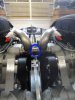
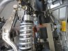
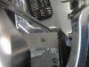
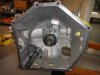
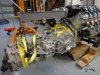
My clutch is finally installed and the Graziano transmission bolted back onto the LS7 engine.

This is the first time I have ever installed a clutch. The actual installation process was pretty easy and only took about 3 hours, although this did include a lot of fiddling around trying to get the transmission output shaft lined up and threaded through the clutch splines. Here's what I learned/did:

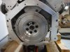
- The pilot bearing goes into the center of the output end of the crankshaft on the engine, in the center of the flywheel.
- The flywheel is mounted using special flywheel attach bolts. One brand of bolts is "arp"
- The instructions for the flywheel attach bolts say that you must use loctite 242 and a special torque lubricant under the heads of the bolts in order to achieve the correct torque of 85 ft-lbs.
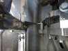
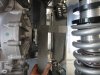
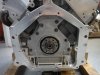
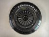
- The clutch plate assembly as supplied by RCR is pretty much self-aligning; it is not necessary to use a clutch alignment tool. I used a universal clutch alignment tool, but I don't really think it helped.
- The bolts used for the clutch plate assembly should be better than grade 8.8. There are different references in different places as to the appropriate torque on 6mm clutch plate assembly bolts, but all the references I saw were over the recommended maximum limit for either grade 8.8 or grade 12.9 bolts. These bolts are installed using loctite, so they shouldn't go anywhere. I personally think it is more "dangerous" to stress these bolts by over-torquing than it is to torque them up to their maximum published limits and rely on loctite to keep them in place, so I torqued mine to 12 ft-lbs (the recommended maximum for grade 12.9 bolts).
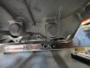
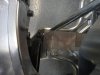
- There is a second output shaft on the transmission which is used for four wheel drive. It can be ignored on our cars, but it may be necessary to shave down some of the boss material on the side of the oil pan in order to clear the shaft. Mine came from RCR with this work already done, but if you have to do it yourself, I would recommend trial mounting the transmission and doing any shaving before trying to install the clutch.
- Getting the transmission properly lined up so that the splined output shaft goes into the splined receiver on the installed clutch is a pain, but by first lining the shaft up at the right height and then fine-tuning the angle using a load-balancing tool on the engine hoist and sighting along the seam between the transmission bell housing and the mounting adapter, I was able to get it to work. It helped that the engine was out of the car, so I could stand in front of the engine, reach across the top to the transmission and kind of "hug" it into place as it was hanging from the engine hoist.
- The flywheel bolts are 11 mm and have a 12-point head, which my 1/2" 12 point socket fits perfectly.
- When tightening the bolts on either the clutch plate or on the flywheel, use a criss-cross pattern (tighten a bit on one side, then go to the opposite side, then 90 degrees, then opposite, etc.) Gradually tighten until everything is torqued to final values.

Here is a list of parts/supplies that I used:

1) Flywheel and clutch $2,145, supplied by RCR
2) Pilot bearing (can be supplied by RCR, but I actually had one already in the crate engine as supplied via RCR)
3) Starter Ring Gear Audi part no. 079105223. $238 Audi Parts - genuinevwaudiparts.com
4) Flywheel bolts arp# 330-2802 $25 for a set. All Keywords: 330-2802
5) Clutch plate assembly bolts socket head 12.9 grade 6mmx70mm $0.24 ea. Chrome Bolts, Stainless Steel Bolts, Metric Bolts, Socket Head Cap Screws, Grade 8 Bolts, F911 Bolts
6) Loctite 242 $8.79 bottle (ebay)
7) arp ultra-torque assembly lube $1.99 sachet ebay

The starter ring gear can only mount one way on the clutch assembly.

I forgot to get a picture of the clutch assembly mounted on the flywheel, but basically if you look at the picture of the clutch assembly on the table and then picture it on top of the picture of the mounted flywheel assembly, you get the idea. The clutch is mounted with the starter ring gear on the side furthest from the engine.
 

Attachments

  • DSC05081.JPG
    DSC05081.JPG
    95.4 KB · Views: 415
  • DSC05083.JPG
    DSC05083.JPG
    87.4 KB · Views: 440
  • DSC05127.JPG
    DSC05127.JPG
    86.7 KB · Views: 428
  • DSC05128.JPG
    DSC05128.JPG
    76.5 KB · Views: 460
  • DSC05131.JPG
    DSC05131.JPG
    116.6 KB · Views: 735
  • DSC05129.JPG
    DSC05129.JPG
    113.5 KB · Views: 517
  • DSC05130.JPG
    DSC05130.JPG
    85.7 KB · Views: 400
Last edited:
One thing that just occurred to me: The crate engine came via RCR with the pilot bearing already installed. I didn't check to see whether or not it was installed with loctite or if it is even required? Does anyone know if the pilot bearings need to be installed with loctite?
 

PeteB

GT40s Supporter
One thing that just occurred to me: The crate engine came via RCR with the pilot bearing already installed. I didn't check to see whether or not it was installed with loctite or if it is even required? Does anyone know if the pilot bearings need to be installed with loctite?

Pilot bearings are press fit - there are no bolts to put loctite on.
 

PeteB

GT40s Supporter
Thanks for the pics - I now understand the difference between a $400 clutch and a $1700 clutch: ;)

audi-logo-black.jpg
 
Thanks for the reply. On other projects I have built (not clutches), the outer race of the bearing itself was secured with loctite, to prevent it from spinning in its mount.
 
The engine and transmission went back into the car today, but I was surprised to find that with the center engine mount bolts and spacers tightened up, the modified water pump contacts the firewall.

On further investigation, it appears that there is about a 1/4" gap between the bottom of the transmission and the rear billet crossmember. The balance point of the engine/transmission combination is pretty close to the location of the center engine mounts, so I could push down on the transmission to make it contact the rear crossmember, which rocks the front mounting cradles off the aluminum frame tube and provides about a 3/16" gap between the water pump and the firewall.

Using a carpenter's square, it appears that the transmission cv joint mounts are not square to the cv joint mounts on the axle stubs. On the left side, the transmission is about 1" further forward and on the right it is about 3/4" further forward. I know that CV joints are designed to handle misalignment (that's what they do with a moving wheel, right?), but I'm wondering if it might not be better to be starting with things in alignment, at least fore/aft, as this relationship would not change in operation.

Looking at the center engine mounts, it appears that if the brackets were built in reverse, it would be possible to significantly shorten the spacer, reducing torsional load while bringing the engine about 1" further back, providing more clearance off the firewall and bringing the cv joints more closely into alignment.

The firewall has been polished to a mirror finish, so the picture showing the water pump contacting the firewall looks odd. The contact point is circled in blue.

Any thoughts or advice on this? The center mounts are substantial steel, which is not going to be easy for me to fabricate with the tools I have and I'm not very good at welding. Should I just rock the engine back and put some shims under the front cradle mounts and ignore the cv joint alignment? Or bite the bullet, move the engine back 1" or so and build up some new center brackets?
 

Attachments

  • Dsc05132.jpg
    Dsc05132.jpg
    60.1 KB · Views: 472
  • DSC05133.JPG
    DSC05133.JPG
    74.5 KB · Views: 353
  • DSC05138.JPG
    DSC05138.JPG
    83.7 KB · Views: 324
  • DSC05134.JPG
    DSC05134.JPG
    89.3 KB · Views: 333
  • DSC05137.JPG
    DSC05137.JPG
    94.4 KB · Views: 365
  • DSC05135.JPG
    DSC05135.JPG
    80.5 KB · Views: 353
  • DSC05136.JPG
    DSC05136.JPG
    66 KB · Views: 304
  • DSC05139.JPG
    DSC05139.JPG
    91.2 KB · Views: 320
  • DSC05140.JPG
    DSC05140.JPG
    71 KB · Views: 321
Last edited:
That first picture is making my brain hurt. You need to shoot from a different angle before my head explodes like that scene from "Scanners"...

JR
 
Dave.

if you move the engine back you will have issues with the trans and the bodywork.

The misalignment on the axles/CV is of no issue at all and is normal...even the vaulted GT40 had misalignment and almost every car on the road does too ...if you move the engine back that far you will create a whole lot of other knock on effect issues.
Here is a full factory LMP1 Acura and RedBull F1 axle misalignment...I think we are pretty safe with the SLC...wink
http://www.gt40s.com/forum/383252-post5.html

The position of the engine as it sits is the best compromise we found....mid engine packaging is always tight...especially when some of the drivetrain parts are not the ones that the car was originally designed around...ie: Graziano ,We have to take many variables into account with every different transaxle on the market and making the SLC engine bay accommodate them all.
 
Last edited:
Thanks for the advice.

So, in my case, would you suggest I just tilt the engine/transmission to get a small amount of clearance between the water pump and the firewall, or go for slightly longer bolts on the middle engine mount and add a washer or two to the spacer?

Keeping in mind that tilting the engine/transmission results in the cradle not sitting quite square on the aluminum tube. . .
 
A couple of washers will do the job...you want minimum clearance to the waterpump

Once bolted in place all will be well

NO tilting EVER....
 
Dave I finished my x-member and installed it this evening we should have everything all bolted up in the morning I will let you know how ours fits. The x-member was about what I expected I used a four link bar off the rack put hiems on It and installed it between the left and right rear connecting points for the vertical adjusting rods that go from the lower chassis point up to the x-member above the engine. This gave me a cross member while I cut the aluminum one out. [glad I did It that way] because as I suspected as soon as I made the first cut when I was just about threw It bound down on the blade locking things up. A couple of turns on the arm and I had perfect alignment with an even saw blade gap top to bottom with no movement at all while I made the x-member. The x-member is cross bolted using three bolts per side and incorporates two anchor points for tying it down while in the trailer. I took some measurements and looked at Frans billit piece which Is very nice and figured It was going to be close my x-member is made of 1x2x120 wall square tubing and mounts beneath the original x-member of which I did leave 6'' on either side probable giving me 3/4'' more clearance then the billet piece I will know for sure in the morning how things fit. I took pictures as usual I will work at getting them posted....................m
 
We installed engine and transaxle back in the slc! surprise with almost no issues. Dave my brackets for the adapter are on opposite sides and everything lines up with out the need for the bushings that I see on yours. I was surprised to see that my brackets were switched the opposite of yours and even more so when everything bolted right up. I measured from the center line of the engine, and to either side on the chassis it is within a 1/16th of an inch, close enough I think. The x-member worked like a charm. I have as I guessed, probable around 3/4 '' clearance from the grazziano to It. The only issue I ran into was while installing the c/v shafts on the grazziano side the end tin cover hit a portion of the stubb axle where the bolt goes threw causing it not to fit flush. We popped one side off to check and it fit like a glove. I called Fran [I actually talked to him in person].............Ha Fran!............. and he said that they just removed them and didn't use them. I now am looking at the exhaust and see why It Is so much easier to run It out the side. I will get the brake lines diffuser and everything back on probable the clam as well to decide what to do:thumbsup:
 
hello, considering an SLC and trying to learn! I am assuming this Grazziano is the Audi R8 box but I dont know that. Can someone point me to info, ratios, final drive, etc. Thanks all!
 
Back
Top