Ok, want to run an alternator idiot light but have the backup of the resistor in line incase the light fails. What size (resistance/wattage) resistor to wire in parallel?
Come out of your office, make a right, then another right, you should see the R&D department, make sure they are all gone home (they usually have their thumbs up their asses any way) and raid their stash of resistors /ubbthreads/images/graemlins/grin.gif /ubbthreads/images/graemlins/grin.gif
Can one of you guys explain why you would need a resistor in parallel? Seems like unless whatever is driving it is a current source (tries to supply the same current regardless of load) or you've got some kind of ECU with a lamp test that won't let you start the car if all the lamps don't test good, there shouldn't be any need.
Circuit diagram perhaps?
At 12V, a 500 ohm resistor would draw 24ma and dissipate .288 watts, so a 1/2 watt resistor would suffice. But I still don't see why you'd need it...
OK, never mind - Google to the rescue. The alternator is energized through the idiot light. Obviously I've never had one of these burn out on me /ubbthreads/images/graemlins/tongue.gif
So now the question is how much current does the alternator need?
I'm not real sure about the current requirements, but I have used a 9v battery (from a radio type) to energize the field in an alternator when the battery went completely dead and I had to push start the car.
if i could figure out windings in the alternator I could prob calculate the excitation current - - - but that sounds like too much work!!
thanks Farhad - it's off to R&D for a little midnight auto supply!!
Gents, you probably can get away by using a 1 Watt resistor. But as all things in elctronics it is the CYA factor /ubbthreads/images/graemlins/grin.gif Kind of like using a 24v rated Cap in a 12V circuit. Design guys would call it the safety factor /ubbthreads/images/graemlins/shocked.gif
Well electronics being my game I might as well put in 2 cents worth.I like to describe alternator operation as follows. The high current output is permanently connected to the battery.Therefore the output current is totally controlled by the field coil circuit which contains a regulator and varies output current (dependent on battery state of
charge and electrical demand).Output voltage is also regulated to a maximum 14.5 volts or so.
Now the power feed to the field circuit is via the ignition switch and idiot light in series.Therefore if the idiot light globe blows no power is supplied to the alternator field circuit and hence no charging.Now if a parallel resistor is placed across the idiot globe, and the globe should blow, power is still supplied through the resistor.Ok so how do we calculate the resistor spec.
assume 3watt globe find current I=W/V =.25A or 250mA
resistance R=V/I = 48 ohms
Now if you put a 48 ohm resistor in parallel with the globe
the current will be shared equally by the globe and the resistor but we want the globe to receive enough current to glow so the resistor value can be set at 250 to 500 ohm and if the Idiot globe blows at least some alternator output will continue even if it is lower than normal.
Regards Ross
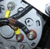
Just want to check my wiring. I've attached a picture of my alternator ...I understand from above that the large output cables (1) go onto my battery ,the field (2) should take it's power via the idiot light on my dash,- so what is the other connection (3) marked STA for ? Also when I first got this engine (alternator included with it) there was what looked like a capacitor between the FLD and the alternator chassis - is this for interference suppression or something. I still have it somewhere just curios.
May as well ask while we're at it....see the post labeled GRD (ground). Needed? Or just insurance in case the alternator bolt makes poor contact to the casing?
You need the STA(stator)wire (a switched hot) to excite the alternator.
Check with an alternator shop first, before you blow up the diodes, like I did in mine! /ubbthreads/images/graemlins/blush.gif A good power source is critical here.
After a bit of searching the net ,I discoverd that the Stator is the windings in the centre of the armature and the field is the outer coil fixed on the outside.
I had assumed these would both be connected inside.
Mike : I'm pretty sure that having the extra earth posts on the back are just for convenience (For other ancillaries) as the huge bolts through the case to the engine block should be a pretty decent earth. Also when mine arrived from the junkyard it had the Capacitor thing connected to it.
Check your search of the net again. I believe you will find that it is the outer coils that are the Stator (they are stationary) and the inner coils are the field coils (more properly known as the Rotor coil). So your assumption was right.
A point about the need for a lamp connected in series with the Rotor coil. If this lamp blows the Alternator may still kick in due to the Residual magnetism of the Rotor. Once the Engine rpm, and therfore Alternator revs, are raised the rotor is capable of being self excited thus powering up the main Stator coils.
But, wait a minute. Does the alternator light glow all of the time or does it only glow when there is something wrong with the alternator, like the voltage being too low? Unless I am mis-remembering how idiot lights work (I've only had a gauge for years) something doesn't sound right about this whole discussion about the alternator being energized through the idiot light. Please edify me!
Never mind, it just dawned on me that the initial excitation comes throught the globe, but then the alternator output excites itself, the globe goes out as this is no longer needed, and away we go. Now if the alternator stops exciting itself, it will draw from the system through the globe causing it to glow and telling the driver, "Hey your alternator is no longer putting out enough juice to excite itself!" Sort of sounds like electrical masturbation doesn't it
Lynn,
I just bow my head and shake at your wit. /ubbthreads/images/graemlins/smile.gif /ubbthreads/images/graemlins/smile.gif /ubbthreads/images/graemlins/smile.gif
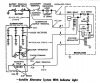
So I'm still fighting with my alternator. The first one I had in the picture had a broken diode inside so didn't work. I have replaced it and also got a regulator which I didn't have before and the shop gave me a wiring diagram. It is now charging but only if revved up to about 2000 rpm and even at this rpm if you switch off the master battery cutout the engine starts missfiring. I then tried measuring the voltage at the stator and it seems to be just 4 volts is this normal ? - the field seems fine on 12-13 volts. My wiring is as the diagram indicated anybody know a source where I can double check the diagram is correct ? I'm suspicious as it says the idiot light resistor should be 15 ohms - I had to find a 22 watt one as a 3 watt started smoking !
15 ohm is correct for this type of ford usa alternator,the current through the bulb only is not enough to energize the field.normally this resistor is build in the wiring of the cars.Do you have an regulator specific for this alternator.the stator terminal is normally about half of the output voltage and is used by Ford to heat the choke on the carburators.No other function to my knowledge so in your case this terminal has no wire.You can find a correct wiring diagram in most ford usa shop manuals 60'to 80'I can help you on one if you want. /ubbthreads/images/graemlins/smile.gif

")