Audi adapter plate.
This is a rover V8 to 016 plate I made (on a CNC router no less).
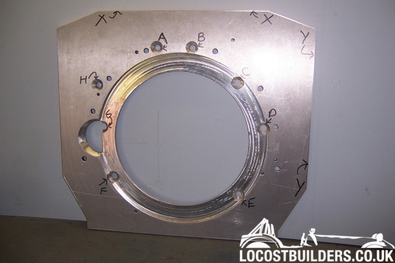
If you draw out ABCDEFGH positions, as described in the notes below, on a piece of card, you can compare that to your adaptor
The photo is taken looking at the adaptor plate from the engine side, I.E. you are looking into the box bellhousing, actually fitted behind the plate in the view. Unfortunately, the bolts do not appear to be on any sort of PCD, so I have to dimension as follows:
Distance from:
top reference XX to box input centre - 250 mm
RHS reference YY to box input centre - 250 mm
Distances from references to trans bolt centres:
Hole A (to suit 12 mm bolt)
AX - 70 mm
AY - 296 mm
Hole B (to suit 12 mm bolt)
BX - 69 mm
BY - 227.5 mm
Hole C (to suit 12 mm bolt)
CX - 135 mm
CY - 140.5 mm
Hole D (to suit 12 mm bolt)
DX - 221 mm
DY - 88 mm
Hole E (to suit 10 mm bolt)
EX - 356.5 mm
EY - 131.5 mm
Hole F (to suit 12 mm bolt)
FX - 333 mm
FY - 390 mm
Hole G (to suit 12 mm bolt)
GX - 229 mm
GY - 411 mm
Hole H (to suit 12 mm bolt)
HX - 144 mm
HY - 417 mm
Please note that all bolts are 12 mm, except for position E, which is a 10 mm Bolt.
Obviously you will have to make your own arrangements for locating dowels or other means to ensure concentricity of the box input with the engine output and for starter motor clearance, depending on the engine you wish to mate to.
Usual disclaimers, the above is what worked for me, on the actual case I had, individual circumstances may vary!
I have in fact since managed to get a look at an original VWSA drawing of what is supposed to be the trans bellhousing I have, and some of my measurements varied from the drawing, so either the VWSA drawing is wrong(!) or some cases did vary?
Cheers
Fred W B