The question is if the vent will vent the air which if there is positive pressure (as I have been stating the entire time) than how in the world is the air going to do a 180 degree turn when the air on the top of the car is (in laymans terms) pushing down as well and thus when the air runs over and past the hole it will effectively PULL air OUT instead of pulling air in (that is with me assuming that the aero on the SLC was designed to still have the air attached to the car going when running down the back). I could understand IF the engine bay was NOT pulling air IN and was full of NEGATIVE pressure or at least opposite to the air flowing on top of the skin. Simple IE: if air is moving firewall to tail / ports and air is moving on the same direction on the skin of the car how aerodynamically speaking does the air pull a 180 turn in such a short space? Wouldn't that really cause a lean situation? I'm sure some time on tuning and it could be overcome BUT that doesn't mean that the situation doesn't exist or isn't happening again unless I have seriously misunderstood everything you guys are saying and that pic proved.

- Forums
- GT40 Replica Manufacturers' Corner
- RCR Forum - RCR40/SLC/917/Superlite Aero
- The SLC Clubhouse
You are using an out of date browser. It may not display this or other websites correctly.
You should upgrade or use an alternative browser.
You should upgrade or use an alternative browser.
Air intake tube routing for the race tail?
- Thread starter Eric McClellan
- Start date
Well, I will take that under advisement. By the way, how does your car run?
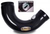
The inlet tube doe not have to be run straight back. There is at least one SLC that has the inlet tube going in front of the rear wheel. Here is a photo of a curved adapter w/MAS. Also you can get a flattened adapter to lower the profile for more clearance.
Attachments
Last edited:
The inlet tube doe not have to be run straight back. There is at least one SLC that has the inlet tube going in front of the rear wheel. Here is a photo of a curved adapter w/MAS. Also you can get a flattened adapter to lower the profile for more clearance.
That flattened adapter is the Corvette C5 airbridge.
I have an airbridge. It doesn't fit. The angle is about 15* too steep for it to work without significant modifications, which of course is plastic and I cannot rework plastic.
However, I do have a new idea that might work and requires minimal effort routing wise.
The idea is to place a sharp and shallow 90* coupler from the throttle body pointing down and away at roughly a 45* angle. This places the air filter (with a short 8-10" pipe with MAF housing) right near the connection of the trans and engine. I'll need a small plate to block heat from the LS7 manifolds, but in theory it looks promising.
I also have the race tail, clearance is a nightmare. What about using a 4" to 3" reducer coupler off of the throttle body and run 3" intake tubing terminating at the filter? Would this starve the engine for air and if so what about using a inline bilge fan to force air down the intake tube?
I also have the race tail, clearance is a nightmare.
as long as you arn't trying to just stick a straight tube on it clearance is fine - just weld up a pipe and run it down to infront of the rear tire. good cold air source. lots of us have done that.
Seems as if I WASN'T WRONG and some feathers should NOT have been ruffled. I asked a legitimate question about aerodynamic (and in this case the lack there of) theory behind such an OBVIOUS DESIGN FLAW and well here we are. Lets get something straight and put some in EGO CHECK TIME. MY build (which at current involves an 1979 FIAT 131 Super that is going through a full on ABARTH conversion and before that I built a caged 02 BMW M3 track rat (which was the cause of my many sleepless nights where I faced this very issue so I was speaking from real world experience. I have posted pics of that car on here before. It still is on one of the sponsors I had web site as a trophy car) and a E30 M3 resto. which was sold long ago. My truck is working wonderfully if that's what you were referring to. Guys just because I don't currently own an SLC doesn't give any of you the right to talk down to me or be a passive aggressive tool especially when I WAS RIGHT ALL ALONG :thumbsup: . Those builds also afforded me the luxury of being able to laugh my A$$ off at what you guys pay for things (full retail is for suckers) and the idiotic value some of you put on your cars (I just leave the rapier cars as all the proof anyone needs). Again I didn't mean any attack to the OP but was seriously asking about his reasoning for such an obviously faulty design. Maybe there was something going on I wasn't aware of BUT THAT WASN'T THE CASE WAS IT!
People really need to either lighten up and realize that sometimes a question can be taken at face value. Either way I got the answer I was looking for and really there is no need for me to continue or for anyone to adress me any further in relation to this.
People really need to either lighten up and realize that sometimes a question can be taken at face value. Either way I got the answer I was looking for and really there is no need for me to continue or for anyone to adress me any further in relation to this.
Why not oval the tube over the fram rail and return to round after or use a halltech intake over the bar.
It's too quick of a transition to really be useful or doable frankly.
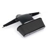
Here's what I did come up with... It's not pretty, it's not elegant... It does however, work.


Ken Roberts
Supporter
It's gonna suck in the hot air from the exhaust in that position unfortunately.
It's gonna suck in the hot air from the exhaust in that position unfortunately.
See my previous post about the heat shield.
Heat shield or no, I agree with Ken that that area is all hot air, all the time.
Also, I assume you are going speed density? The GMPP controller kit is pretty specific about needing a specified length of straight tubing before and after the MAF sensor. SD would obviate the need for the MAF sensor, and intake setups like the one you have with so many bends would probably work fine. I've even seen cars with a filter mounted directly on the TB (running SD, obviously). But if you are running the stock MAF setup from the controller kit, the setup you have there is clearly not per spec. What that means isn't clear, but I would expect driveability issues, at a minimum.
It will be interesting to see how that works, if you keep it.
Heat shield or no, I agree with Ken that that area is all hot air, all the time.
Also, I assume you are going speed density? The GMPP controller kit is pretty specific about needing a specified length of straight tubing before and after the MAF sensor. SD would obviate the need for the MAF sensor, and intake setups like the one you have with so many bends would probably work fine. I've even seen cars with a filter mounted directly on the TB (running SD, obviously). But if you are running the stock MAF setup from the controller kit, the setup you have there is clearly not per spec. What that means isn't clear, but I would expect driveability issues, at a minimum.
It will be interesting to see how that works, if you keep it.
If you look at the pipe itself, it has the MAF installed. It works and it runs, no codes thus far. It's 10" downline from the TB per spec from GM.
I'm not sure what you mean by "so many bends"... it's one bend.
Eric
If you look at the pipe itself, it has the MAF installed. It works and it runs, no codes thus far. It's 10" downline from the TB per spec from GM.
I'm not sure what you mean by "so many bends"... it's one bend.
Eric
I wasn't sure if what I saw was the MAF sensor. But if it runs well, and makes good power, that's what matters!
I wasn't sure if what I saw was the MAF sensor. But if it runs well, and makes good power, that's what matters!
We'll see how it does. I plan on chassis dyno'ing it here soon. Did the engine dyno a while back.
Similar threads
- Replies
- 3
- Views
- 679
- Replies
- 3
- Views
- 1K