And so it begins...the AP build.

Chris Kouba

Supporter
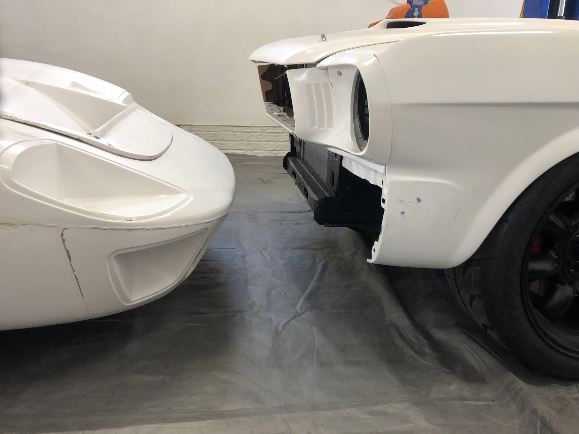
Interesting perspective with the 66 FB.
7200b255-691e-44d3-9cdc-739702292842-jpeg.128473

One of my own personal favorites:
AMWts8BLq2WY1x_siwhWWqxyWP5uPotWhWcYbS9ZvJrjX0TnOXtCsu2y47tmMRNV0XNS58ZS_wv18pycWbM4DVmrOGbn_iLkPE0Tg2fMzUL1Cvef-LsBokrqWC05AhDwZHPNNyhtbSoaQ6Nz2NyDuJVtySBV1Q=w1669-h937-no


and a better comparative perspective:
AMWts8CVg4qBx-Ebh5GsG_l18kIktL0ztEeM6G_iLYZZ33vkhnZj7v-3SA3SvUw1LIa4MFkaJqz6RqIT_6qskbfPjRgZX9uekF0rSnG8I3L6UjvjpIwwUMlx1W_6R1yagPDh7LTYPtMhkNROjzrfF5ExC2R86A=w1670-h937-no


It's not even belt-buckle height!
 
I wasn't aware that Prestige was working with Coyote motors now. Waiting to get my estimate for a Borla FI 8-stacked motor. I know Chris has done them in the past...so it should fit.
Meanwhile, I had some fun with different colored epoxy primers. The 66 might as well have a little style as it gets shaken down. The plan is to work out all the bugs and have it in paint early 2024.
350rprimer1.JPG
350rprimer2.JPG
350primer3.JPG
Time to stop the head scratching and get to work on the GT.
 
Its a fiberglass part that took a fair amount of massaging of the bumber, mounts, and mount holes to get right. The fiberglass hood fit pretty well right off the bat, but I had to add 1/8" of width to the passenger side. I suppose this experience of working with fiberglass may come in handy in the future.
 
I received my quote from Prestige for a 530hp 8 stacked and injected 363 complete from pulleys to pan. Prices seem to have gone up a little since they built my Mustang's motor in early 2021!
 
Every journey begins with a first step. In this case, it begins with a bath. I had brought up the subject of fiberglass prep in the forum hosted by the company I get most of my primer supplies from (Southern Polyurethanes). Most people that know more than me suggested lots of scrubbing and degreasing due to mold release that could mess things up down the road. I also was able to ask one of Chris's inside guys on how he preps the bodies. He mentioned that the mold release AP uses is water soluble and that he just powerwashes things prior to starting bodywork. I rolled the thing out and hit it with my foam cannon and dish soap. I used up a bunch of used red scothbrite pads to scrub and rough up the surface. It actually looks a lot better now!
bath1.jpg
bath2.jpg
 
I’m not sure I’ve ever spent so much time in the garage and felt like I got so little done. Started establishing a centerline on the top of the spider that I continue to the front of the windshield and top of the pedal box. I can’t get a gap that I can work with at the front of the clam. The rear wheel isn’t centered in the wheel well either. I feel like the rear clam needs to be remounted on its hinge after moving it rearward 3/16”. I just need to get the gaps as close as I can get them via panel movement, and finish them with filler
IMG_0042.jpeg
IMG_0043.jpeg
IMG_0058.jpeg
IMG_0069.jpeg
IMG_0072.jpeg
IMG_0084.jpeg
IMG_0083.jpeg
IMG_0042.jpeg
.
 

Randy V

Moderator-Admin
Staff member
Admin
Lifetime Supporter
Getting the body mounted is always a royal pain.
one thing that may help is to spec that spider 1/8” off of the Sill. Same for the rear clip - should be spaced up 1/8”.
This isn’t a great photo, but shows what I had to go through to get my shut lines and body alignment to work..
IMG_5233.jpeg
 

Randy V

Moderator-Admin
Staff member
Admin
Lifetime Supporter
Front clip should also be spaced up by 1/8” from the sill.. It’s a long process to fit these correct (far from perfect) body panels to a completely perfect CNC Chassis..
 
I'm not sure how much jig work is used for the tube frame chassis for my car, but I'm sure it isn't perfect. One thing off the bat I seem to be noticing is that the driver side a-pillar bar seems to be closer to center line that the passenger side when viewed from the front. I have the centerline of the spider established already, so it seems like this isn't just an optical illusion.
I noticed that the bottoms of my spider legs aren't completely flat. There is a lip midway through that seems to want to hit the frame when adjusting the legs outward, and also makes shimming cumbersome. I'll probably flatten it out with a little fiberglass filler to make things easier.
 
Unbolted the rear clam hinge after strapping the front down to the lift. Gaps are workable now! At first I thought I was going to have to redo the frame where the hinge bar slides in be it would seat all the way with the clam in the new location. However, I think it isn’t able to move all the way down into the groove because the body is warped bad enough in that area that the bar hits the body panel before it seats. I going to get the warp out of the fiberglass and then see where things stand.
IMG_0104.jpeg
IMG_0110.jpeg
IMG_0104.jpeg
IMG_0110.jpeg
IMG_0109.jpeg
IMG_0107.jpeg
IMG_0106.jpeg
IMG_0105.jpeg
IMG_0113.jpeg
IMG_0115.jpeg
 

Randy V

Moderator-Admin
Staff member
Admin
Lifetime Supporter
If you already have the windshield, I would advise that you place it in the spider, making sure you have a gap of 1/8 - 3/16” top and bottom. Then cut a 2x4 board to go between the floor (spine) and the bottom of the spider to support it. The fiberglass spiders are famous for sagging and making your life a total hell when you’re trying to fit the doors. Also, do your fitting of the doors and rear clam with the weather stripping in place. You can see my 2x4 support in this photo. My shut lines were all 1/8” and sanded out to 3/16” before it was painted.
IMG_5465.jpeg
 
Walking in circles…around the lift. I feel like I’ve spent more time looking at this thing trying to figure it out then I have actually working on it! Basically, I moved the rocker all the way back towards the rear tire. Then made sure the gaps between the rocker’s rear and the front of the tires were even. Measured the width of the bottom of each side of there rear clam and found out the driver’s side is 5/16” shorter than the passenger side! I also found that the bar for the rear hinge was over 1/4” too short, which was probably putting some strain on the inner fenders when tightened down. So that came off and got lengthened. I finally started making some headway after I measured 15” from the back of the rocker to show where the front of the clam should sit. Then measured 3/16” from there to show where the rear of the b-pillar should sit. Baby steps!
Oh…and I set the rear toe to zero so my measurements would be more accurate.
IMG_0136.jpeg
IMG_0145.jpeg
IMG_0158.jpeg
IMG_0163.jpeg
IMG_0164.jpeg
IMG_0165.jpeg
 
I remeasured the clamp cutout locations and they may be close enough...unless my OCD gets the better of me. Especially since you can only see one side of the car at a time. Initial gaps will be set at 3/16", as I did on my 66 fastback project. They will tighten up a little after bodywork, and everyone talks about how fiberglass has a mind of its own when it gets in the sun. I've been thinking about redoing the hinge mechanism for the front and rear clams. I'll probably mount a pillow block bearing to each side of the original mount to make it a little more accurate and secure in its function.
I was able to tack down and order some higher quality clam alignment pins from RCR. 6 are on the way to help with clam alignment.
alignment pins.jpg
 
Back
Top