AP mk1 twin turbo

66"

It's about 1" short from the back of the side fuel tank covers and 2" short on the front.

At that 66" there is an angled tube back to the bottom of the inner sill and a horizontal back to the top inner sill.

From the high picture, you can see the back of the side is plumb, and the front is angled.

THe extra inch gives clearance to conceal the tube.
 
Started trying to put together my engine and ran into a few incompatibilities,

The Man-O-War block has the bosses drilled for the spider, but not the clearance for the dog bones, so I need to buy different (link bar) lifters.

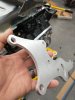
The timing set requires modifying the cam thrust plate to use counter set bolts, so I can't close up the front of the engine.

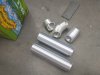
The block docs call for Moroso Chevy oil restrictors, no mention on when or why, and the Moroso docs say NOT to use them with hydraulic lifters. Need to research this because I am running Hydraulic rollers.

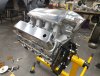
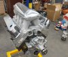
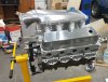
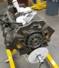
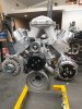
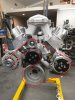
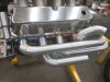
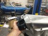
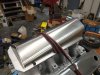
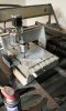
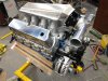
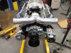
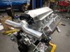
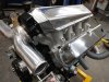
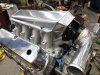
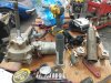
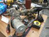
But I did check the cam degrees, and it's spot on, and took the opportunity to get some glamour shots.
 

Attachments

  • Glamorshot 3.jpg
    Glamorshot 3.jpg
    670.7 KB · Views: 247
  • Glamorshot 2.jpg
    Glamorshot 2.jpg
    509.3 KB · Views: 241
  • Glamorshot 1.jpg
    Glamorshot 1.jpg
    621.9 KB · Views: 199
  • Degreed.jpg
    Degreed.jpg
    275.5 KB · Views: 197
  • Turbos.jpg
    Turbos.jpg
    673.1 KB · Views: 220
It's a constant wait on engine parts.

Lifter situation is sorted, and the cam fully installed. I had to surface grind the thrust plate to get .007" endplay. It had zero.

Heads are on but I'm waiting on an adjustable pushrod to get the optimum length.

So I'm piddling with other fussy bits. My novel 180 degree, 2 separate header setup (without slip joints) takes a bit of work. I have a tube layout where all of the L bank goes to the top flange, and the R to the bottom (or vise versa, reversing the rotation direction) and the collector on the L and R each get a circular patern firing order, rotating in opposite directions. AND I have 2 independent headers with formed stainless dimple gaskets, so no leaks with turbo backpressure. I made a die for my Cobra to make these type gaskets from 20ga 304.

I need a heavier and bigger brake for .125 aluminum 4'+ long, so I'm making one. I'll get some round stock to make the die with, welded to the 2 tubes.
 

Attachments

  • zbrake.jpg
    zbrake.jpg
    416.7 KB · Views: 187
  • zheader flange.jpg
    zheader flange.jpg
    365.4 KB · Views: 221
Valve train is in and I'm making accessory brackets. Still waiting on a transaxle.

The pushrod tips were given a drop of assembly lube, and I'll pour a quart of oil on the rocker's pivots and tips before I start it.

For the alternator, I'm using a GM and the bracket has one bolt to the head, 2 to the water pump at the port, and with a machined doweled spacer to the bottom of the timing cover.

The front compressor bracket will have 3 bolts on the head to 2 of the back ears, and the front will catch 2-3 of the waterpump bolts to 2 front ears with enough back and forth flex to not bind anything. The top tensioner/idler might be integrated with the front bracket. Not sure yet until I have the compressor hanging as it will.
 

Attachments

  • accessories.jpg
    accessories.jpg
    392.3 KB · Views: 172
  • belt.jpg
    belt.jpg
    403.7 KB · Views: 185
  • valve train.jpg
    valve train.jpg
    403 KB · Views: 206

Randy V

Moderator-Admin
Staff member
Admin
Lifetime Supporter
Looking good.
Just make sure whoever is building your headers is aware that you are using port adapters (or are those header flanges?) on raised port cylinder heads..
 
I'm doing my own headers, and those are flanges, but not the ones I'm using. I have some with only the larger bolt pattern and squared up ports that will be easier to mate to the tubes.
 
While I was waiting on parts, I had the 3D printer spitting out pieces. I printed a half flange, straight and 45's of the 2 radius bends Stainless Bros sell in 321. The straight pieces can be cut to length, and they all fit together with a little friction so you can play with the design before cutting up stainless.

None of this is anywhere near final design. Just showing off my printed legos. I need to cad up some 15 deg and 20 degree. If I went much more than 45 degree I would need support and I didn't want to have to clean that up or waste the filament.
 

Attachments

  • header mock up1.jpg
    header mock up1.jpg
    295.8 KB · Views: 200
  • header mock up3.jpg
    header mock up3.jpg
    357 KB · Views: 189
  • header mock up2.jpg
    header mock up2.jpg
    346.1 KB · Views: 199
The intake manifold as it sits is not going to work. If I face the intake rearward, the length and slight downward angle of the throttle body will be in my precious bundle of snake's real estate. If I try to face it forward, it's way too long and will be way inside the cockpit. So I'm fabbing a new top, much shorter and and angled downward much more so the throttle body to the TEE to each intercooler will not intrude into the cockpit... or at least only to an acceptable amount.

I'm also working on a crossmember and motor mount assembly, and when I've finished it today, I'll roll the engine back right side up and bolt the water pump on for good and finish up the accessory brackets.

My tig welder doesn't have the stones to weld 1/4" aluminum base plate for the new manifold, so I need to hook up my spool gun and get a little practice in on it. I think I could do prettier mig welds than tig anyway.
 

Attachments

  • IMG_20221108_204646.jpg
    IMG_20221108_204646.jpg
    384 KB · Views: 150
  • IMG_20221107_132749.jpg
    IMG_20221107_132749.jpg
    414 KB · Views: 163
I've recently dug up my little toy CNC router and used it to cut a 1.4" 6061 front bracket with mount for an adjustable idler.

It uses the same software and computer as my plasma table.
 

Attachments

  • IMG_20221118_204547.jpg
    IMG_20221118_204547.jpg
    185.3 KB · Views: 163
  • IMG_20221118_200911_01.jpg
    IMG_20221118_200911_01.jpg
    220.3 KB · Views: 190

Randy V

Moderator-Admin
Staff member
Admin
Lifetime Supporter
You can always preheat the area with a propane or MAP gas torch.. That does make it a bit less of a user friendly environment to weld in, however…
 
Camera didn't take a very good pic. Sort of soft focused it like they do to hide Tulsi Gabbard's pock marks.

That's sort of what I did. I long arced the 1/4 for a few seconds before I got down on it. I had my little beginers Hobart eazy tig cranked up to 11. I've never had the fan run so long after I've stopped welding.

Welding the 90's and tee straight to the throttle, and this fabbed intake bought be about 5" I think I can live with this.
 

Attachments

  • IMG_20221125_170551.jpg
    IMG_20221125_170551.jpg
    413.2 KB · Views: 160
  • IMG_20221125_170541.jpg
    IMG_20221125_170541.jpg
    402.4 KB · Views: 164
  • IMG_20221125_170534.jpg
    IMG_20221125_170534.jpg
    429.7 KB · Views: 160

Neil

Supporter
"Camera didn't take a very good pic. Sort of soft focused it like they do to hide Tulsi Gabbard's pock marks."

Politics???
 
5052 doesn't polish that well. I should have know that since is also doesn't machine well. But I'll say, it came out better that Tulsi's complexion.
 

Attachments

  • IMG_20221126_201456.jpg
    IMG_20221126_201456.jpg
    424.6 KB · Views: 143
  • IMG_20221126_201444.jpg
    IMG_20221126_201444.jpg
    438.2 KB · Views: 144
I put a granite top on the little cabinet for my lathe tools. I used it and some adhesive backed tape to lap it flat. Where the sand paper marks were, I kisses with a flap wheel on the grinder, then lapped some more until I had sand paper marks on all of the gasket surface.

Lots of aluminum powder.
 

Attachments

  • IMG_20221126_115305.jpg
    IMG_20221126_115305.jpg
    433 KB · Views: 133
  • IMG_20221126_201507.jpg
    IMG_20221126_201507.jpg
    340.6 KB · Views: 165
Jumping around, I started messing with my power steering plans. I had the motor and module, but thought it might be nice to have all of the splined bits and a second motor so if this thing went south I would have a spare before they became scarce.

It turns out, I may use most of this column, ditching the dated looking wiper controls, turn signal switch and ignition key. It all bolts on.

There's a dude in Portugal that sells a module that generated the pulse train that tells the EPS how much assist to give. It includes a potentiometer that adjusts it.

Looks like mounting it with the adjustable height will be a breeze. This will also give a collapsible column.
 

Attachments

  • IMG_20221206_161452.jpg
    IMG_20221206_161452.jpg
    515.3 KB · Views: 144
  • IMG_20221206_160158.jpg
    IMG_20221206_160158.jpg
    487 KB · Views: 141
Back
Top