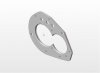
audi 016 reinforcement plate

Guys,

do to the fact that I have received alot of PMs requesting this model, I am going to try to attach it to this reply.


Here goes.
 
Last edited:
if anyone is making these, i will buy one, have paypal ready. I just dont have the equipment to cut the steel, sawzall and holesaws will take forever
 
Jim,

After machining, did the plate remain reasonably flat? Perhaps not entirely necessary, but I would be inclined to machine a silghtly thicker plate followed by Blanchard or double disc grinding to size to ensure flatness and parallel surfaces. Cheap insurance at $40-$60 for the process.

Andy
 
Andy,

Jim Dinner came up with this idea and he was using plain old 1/4" hot rolled flat stock. He's had great success. His plates were made using hole saws and drills bits, nothing extravagant. If your concerned check your flatness on a surface plate using a dial indicator. The thickness can be check with mics.;)

You can buy pre-ground flat stock from McMaster-Carr or any steel supplier.
The rear tail housing only holds the input shaft 4-point ball bearing that controls axle load on only the input shaft. I'm not trying to say this isn't important, but that type of bearing has some flexibility.

My plate was within .001" variation in thickness over the whole surface, but it had a little cup to it, about .003". Once it is sandwiched between the 2 housings it was flat enough for me. :)
 
Thanks for posting file. But I can't read it, and my you beaut FEA software that should read everything is spitting the dummy, as usual...

Any chance you could post it as a .dwg or .dxf format or at least point me to a .igs viewer?

I'm finally at the point where my real GT40 motor is going to be assembled and the 016 will need a toughen up in the next month or so (Quaife ATB + strenghtening case saver plate).
 
Andys,

Thanks for the tip. But I installed both the SolidWorks viewer and then the edrawing viewer and neither of them would open the .igs file! Sigh, will try with AutoCad tonight and see how that goes. How can it be so hard to open what is supposedly an international standard file type that has been around for many a year?!
 

Charlie M

Supporter
I imported the file into Unigraphics NX4 and it worked fine. It came in as a series of sheet bodies but all the detail appears to be there. Thanks!

Charlie
 
Julian,

There should be an option available to select the file type when attempting to open a .igs file with the Solidworks viewer. The AutoCad viewer should be capable of opening a .igs file as well.

If you hit a dead-end, let me know and I'll see if I can save the .igs file as a solid model and send you the Solidworks file (now that you have the viewer).

Andy
 
Andys,

If you could save as a solidworks file and post that up that would be great. I've tried Autocad 2005 + other viewers and not to mention I-DEAS (my FEA software at work) and just can't get it to work.

Thanks,

Julian
 
Julian et al,

I cannot post the Solidworks model. The manage attachments says "invalid file" when I try to upload it (as it's not a file type listed in the choices). Instead, I attached a .jpg file. Keep in mind, the model that Jim provided is only a 3D model, meaning it is not a dimensioned drawing. The .igs and files like .dfx are commonly used for machining programs (depending on the program; MasterCam, Virtual Gibb, etc).

Jullian, drop me a PM with your e-mail address, and I will send you the Solidworks file.

Andy
 
Attachment didn't take. Let me try again.

Andy
 

Attachments

  • audi_trans_plate.jpg
    audi_trans_plate.jpg
    13.1 KB · Views: 677
S Steve,

I don't happen to have a jpg file handy, and I'm not really sure what good it would do you to have a picture. Andy just posted one if this helps. I don't have a drawing of this because I simply put the cast iron housing on a CMM (coordinate measuring machine) and got the data I wanted then I built a 3 dimensional model in Pro-E wildfire. Once I had this done I import the model into DelCam Powermill 8.0 and write a CNC program from this. Since I modeled the part I know what I want for tolerancing so I don't need a print to tell me. All of the little holes are clearanced for bolts so they don't have to be held really tight on position, the 2 little holes near the middle are oil communication holes so they don't have to be perfect. The 3 largest holes in line with each other are for the shift shafts, I modeled these kind of close to the shaft size so if your not going to hold good position increase there diameter. The 2 medium size holes that are some what diagonal of each other are for the dowel sleeve and need to be held tight on diameter and position.

Hope this helps:)

Jim
 
plate
Here is a drawing I did of the elusive plate.
I surface ground them down to about 7mm.
Take them to a clutch shop and throw them on the flywheel grinder.
Happy to email the DXF as long as its not to 3000 members if you know what I mean.

I can guarantee the accuracy.

Jim
 

Attachments

  • STIFFNER.jpg
    STIFFNER.jpg
    22.7 KB · Views: 719
Last edited:
IF you try to never hit the gas pedal while your foot is on the clutch pedal it will last a long time. You must tighten the driveline on a takeoff and do clean shifts with a zero throttle opening. After your foot is off the clutch pedal go nuts, it can take lots of power.

The plate is easy to make and does not need to be really accurate. I needs to surround the pinion bearing area only. I originally made it to cover as much as possible for strength. For the shift rod area for example, one big slot for all three rods would be fine.

The Porsche 944 Turbo has the exact same differential carrier but with four spiders instead of two. This will distribute the load better and should not break the spiders.

Here is my latest build with a BMW v-12 and here is a video;
http://stweb.peelschools.org/sssweb/TTI-WEB/cars/videos/ChassisDriving.wmv
transmissioninstalled.jpg


Cheers;
Jim
 
Back
Top