I would gusset that last one at a minimum. This bellcrank support is taking high energy/low amplitude impulse loads. The support therefore needs to be exceptionally stiff in addition to being strong. An unreinforced piece of angle like that isn't stiff enough (IMHO), it can deflect any which way along the horizontal member. Box that section out and you ensure virtually 100% of the load going through the pivot bolt gets transferred into the aluminum upright.

- Forums
- GT40 Replica Manufacturers' Corner
- RCR Forum - RCR40/SLC/917/Superlite Aero
- The SLC Clubhouse
You are using an out of date browser. It may not display this or other websites correctly.
You should upgrade or use an alternative browser.
You should upgrade or use an alternative browser.
Bellcrank reinforcement plate ideas.
- Thread starter KENS80V
- Start date
Howard Jones
Supporter
I agree with Cam somewhat. That flat stock will yield at the bend unless the load is fed directly into the chassis member by the longer horizontal element (possible) and the shorter vertical element only locates the structure. It would be easy to add a gusset to at least one side and I think that would be a good idea. He is a mechanical engineer after all.
I had considered cutting a piece of oval tubing and gusseting the perimeter of the flat piece on mine. I decided to make it much thicker and out of premium steel (all my materials are 4140) to save some time and complexity.
I found a USA vendor but I suspect that my very small quantity requirement would be expensive. I did not contact them. However a larger diameter round tube could be reshaped into a oval with a press. In any case these are the considerations that I had.
1. Maintain the pivot rod in a vertical position with out any lateral deflection when loaded.
2. Feed the load into a near by and rigid chassis member.
3. Create the necessary bracket that would not flex under load.
Here's the USA tubing manufacture.
http://www.jackson-tube.com/index.php
Last edited:
I was originally going to gusset it, but the aluminum piece I used is 3/8" thick and very rigid. After the installation I thought it would be ok as is since I think most of the load is actually in the frame housing bearing (or whatever the correct term for that part is). The extra reinforcement plate likely takes only a small percentage of the load.
That being said, thanks for the input and I probably will gusset it in the end.")
That being said, thanks for the input and I probably will gusset it in the end.
If Paul could provide photos of his failure we’d have a better understanding of the type of loads going through there.
I wanted to get as much stiffness as possible because I didn’t want my aluminum beam to get wallowed out of round, not because I feared failing the bolt or aluminum structure.
I think it would be very difficult to get catastrophic failure at this location. I just didn’t want to lose any precision of the pivot point.
I’m actually very surprised Paul was able to fail this joint - but again, we don’t know the failure mode or the conditions that led up to the failure.
When I do the other side I'll take a picture of the bushing.
I think it's a solid piece machined to allow the bellcrank shoulder bolt to fit through. That solid piece is then welded to the surrounding frame. I expect Paul's failure was indeed the surrounding frame, not that the solid bushing wallowed out. But only Paul can confirm that.
I think it's a solid piece machined to allow the bellcrank shoulder bolt to fit through. That solid piece is then welded to the surrounding frame. I expect Paul's failure was indeed the surrounding frame, not that the solid bushing wallowed out. But only Paul can confirm that.
Howard Jones
Supporter
It's not a catastrophic failure that is the real problem. It's replacing the solid piece of aluminum housing that would be a major repair. I think that would be best done with pressing in a very hard steel thick wall piece of tubing after boring the hole out to size. Setting that up to do the bore will take some thinking and more than likely a home made jig.
Solve that problem by as Cam says prevent the wallowing out in the first place.
It's only fair to remember that I am speaking from a track only cars experience.
Solve that problem by as Cam says prevent the wallowing out in the first place.
It's only fair to remember that I am speaking from a track only cars experience.
I saw Paul's car at the track Monday and looked at the area his failed.
The bushing did not wallow out. The frame rail the bushing is welded into is where the failure was.
That sounds like an off-track excursion caused an excessively high load. This isn’t a use case these reinforcement plates are designed to mitigate against. Did Paul give any details on how this happened?
Ken Roberts
Supporter
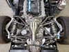
I finally got to finish my version. It matches the look of the rest of the steel tubing in the engine compartment. I just need to tack them together and send them out for final welding.


Last edited:
As with everything else on you build, it looks first class.
Regards Brian
Regards Brian


Ken Roberts
Supporter
Bumping this post so that others will see the various techniques to beef up this area if you plan to track your car.
Unfortunately this part can’t be mass produced. Each car will have subtle differences in length. It must be built in place and then tack welded before final welding.
Unfortunately this part can’t be mass produced. Each car will have subtle differences in length. It must be built in place and then tack welded before final welding.
Last edited:
As an FYI guys to alleviate any analysis paralysis
We never ran a reinforcement brace on the Championship winning SLC and we checked the bearings after each race weekend.
We also activated the blade style sway bars from the bellcrank too
A nice addition guys but not a 100% necessity
We never ran a reinforcement brace on the Championship winning SLC and we checked the bearings after each race weekend.
We also activated the blade style sway bars from the bellcrank too
A nice addition guys but not a 100% necessity
Howard Jones
Supporter
I like this one the best. Except for welding, it is simple and easy to make. I may make some myself if I get to it. I also think that they could be made to fit other SLC's if you left the left end intentionally short by 3/16 or so and made up the difference in situ with washers to accommodate individual variations.
Do you need this? That I don't know. I did mine because I could and I intended to run my car on track for many seasons. The other reason was I didn't want to have to repair the thur hole IF it did in fact wallo out over time. Remember my build predated Fran's championship car and I believe it was the first car started with a track car only in mind. I got the idea from the blue 25 hr Thunderhill car out in California. They did something similar as a preventive measure with very long endurance races in mind.
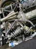
My car (chassis 24) is different than the above, see the picture below. It uses a flat block welded to the top of the chassis rail instead of a thru bushing.
Do you need this? That I don't know. I did mine because I could and I intended to run my car on track for many seasons. The other reason was I didn't want to have to repair the thur hole IF it did in fact wallo out over time. Remember my build predated Fran's championship car and I believe it was the first car started with a track car only in mind. I got the idea from the blue 25 hr Thunderhill car out in California. They did something similar as a preventive measure with very long endurance races in mind.
My car (chassis 24) is different than the above, see the picture below. It uses a flat block welded to the top of the chassis rail instead of a thru bushing.
Attachments
Scott
Lifetime Supporter
I was initially concerned that the aluminum bushing that supports the bellcrank would wear, but I'm not aware of that ever happening. However, I am aware of a couple of cars in which the 2" x 2" tube that supports the bellcrank developed cracks on the joint with the front billet upright. The other end of that tube has a large gusset which supports the toe link and the lower tube doesn't have a bellcrank so IF there is going to be an issue, it's likely to occur at the aforementioned joint.Has anyone actually reported a crack, unusual directional wear, or bent hardware?
These were endurance race cars which had more hours that the championship SL-C. On one of the cars, the cracks were detected during a routine inspection after 180+ hours of racing. Like the championship SL-C. they were running wide slicks (i.e., 345 mm), stiff springs, lots of downforce, and the rear sway bars were connected to the bellcrank. Curbs were ridden and there were a couple of off-track excursions. These types of loads will never be seen in a street car or someone doing track days.
The only thing that you shouldn't do is to cover the weld joints with heat reflective tape.... it will cover up any cracks that might develop.
The support arm is not required for a street or track-day car, but it's easy to fabricate and, other than the one made from right-angle aluminum, all of the above approaches look like they would work. That said, if you're going to the trouble of fabricating an arm, I would replace the provided top misalignment spacer with one that's welded to the arm.
Gussets appear to only be warranted for endurance racing or for nut jobs like me. Adding them is conceptually simple, but it's a lot of work given the amount of heat required. You need to strip the engine compartment to prevent things from getting damaged and I recommend fabricating a steel brace to connect the left/right sides of the chassis and temporary spacers to replace the bellcranks to reduce the potential of warping. I posted my approach here: (65) S2's Build Thread | Page 32 | GT40s
Last edited:
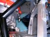
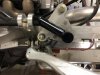
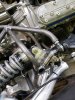
I’ll be posting more pictures of my car in the near future but I thought I’d post A couple pics to this topic. We are rebuilding the cross brace to lower it for the eight in the one exhaust and Builder came up with this idea to reinforce that bellcrank. Seems pretty solid
Attachments
Similar threads
- Replies
- 20
- Views
- 2K
- Replies
- 37
- Views
- 12K
- Replies
- 1
- Views
- 1K