That would work. Need a mill / CNC machine !

You are using an out of date browser. It may not display this or other websites correctly.
You should upgrade or use an alternative browser.
You should upgrade or use an alternative browser.
Chuck's Jaguar D Type Build
- Thread starter CESLAW
- Start date
Standard mill will do ; don't you have any small machining workshop near your place ???? willl be very very cheap to order
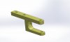
The drawing is almost ok ; I did the CAD with your dimensions !!!!!") the only one to correct is the aperture in beetween the faces of washers
the only one to correct is the aperture in beetween the faces of washers
Material is not necessary a very tensile one as per the form the part have now can be eventually lighten to match nicely to the upright !!!!!
There at my "collegue" small workshop such small work will be done probably for 100 euros the pair !!!!!!!!!!!!!!!!!!!!!!
The drawing is almost ok ; I did the CAD with your dimensions !!!!!
the only one to correct is the aperture in beetween the faces of washersMaterial is not necessary a very tensile one as per the form the part have now can be eventually lighten to match nicely to the upright !!!!!
There at my "collegue" small workshop such small work will be done probably for 100 euros the pair !!!!!!!!!!!!!!!!!!!!!!
Attachments
Standard mill will do ; don't you have any small machining workshop near your place ???? willl be very very cheap to order
The drawing is almost ok ; I did the CAD with your dimensions !!!!!
Material is not necessary a very tensile one as per the form the part have now can be eventually lighten to match nicely to the upright !!!!!
There at my "collegue" small workshop such small work will be done probably for 100 euros the pair !!!!!!!!!!!!!!!!!!!!!!
Thanks Michel. All good points. I am however looking at a different rod end which solve any issues with the steering arm / tie rod connection.
Chuck,
We looked into this issue some time back for the GT.
Jac Mac had some ideas that would not only correct the bump steer, but also allow the Ackerman to be properly addressed. I will see if I can find the thread tonight when I get back online..
@jac mac if you still have your notes or thoughts???
We looked into this issue some time back for the GT.
Jac Mac had some ideas that would not only correct the bump steer, but also allow the Ackerman to be properly addressed. I will see if I can find the thread tonight when I get back online..
@jac mac if you still have your notes or thoughts???
Doug M
Supporter
Chuck, a battery question. Did the RCR design not allow for the battery to be in the ‘stock’ location under the bonnet? Or did your custom pedal and steering work prevent it from being installed there? Also, will it be covered up more to protect it from the elements?
Fine work as always. Just curious.

Fine work as always. Just curious.
Doug
Yea, I would have preferred to put it in the original location. Two problems.
First, the footprint of even the smaller Odyssey battery being used is too large for that area. Second, to lower it one would have to cut out a large section of the tub. In that location it is double walled. Doing so would drop the battery into the foot well and could impair the integrity of the chassis in a higher stress area.

To capture the look of the original we may fabricate a faux battery top that will fit in that location. The positive of the faux battery may actually be connected to the electrical system to provide a point where the engine could be easily jump started. That project however is on the distant horizon.
The original D had a very snug foot box that followed the angled brace. RCR substantially enlarged it so normal people could comfortably fit. There are always trade offs.
A cover for our rear mounted battery is something I have debated. This is a well protected location so it may not be needed. On the other hand it would be an easy matter to add a cover similar to what one sees on most light aircraft batterys
Yea, I would have preferred to put it in the original location. Two problems.
First, the footprint of even the smaller Odyssey battery being used is too large for that area. Second, to lower it one would have to cut out a large section of the tub. In that location it is double walled. Doing so would drop the battery into the foot well and could impair the integrity of the chassis in a higher stress area.
To capture the look of the original we may fabricate a faux battery top that will fit in that location. The positive of the faux battery may actually be connected to the electrical system to provide a point where the engine could be easily jump started. That project however is on the distant horizon.
The original D had a very snug foot box that followed the angled brace. RCR substantially enlarged it so normal people could comfortably fit. There are always trade offs.
A cover for our rear mounted battery is something I have debated. This is a well protected location so it may not be needed. On the other hand it would be an easy matter to add a cover similar to what one sees on most light aircraft batterys
Steering, Part II
The Heidt rack extender kit came with a pair of extended boots. The boot worked great on the driver’s side, but on the passenger side there was a problem. The inner opening of the boot is 2” but the rack is 1 1/8”. The gap had to be filled.

Sea Board (HDPE) was used to make a ‘donut’. A 2 1/8” hole saw was used to cut the outside followed by a 1 3/8” to cut the inside hole. This resulted in a finished outside diameter of 1 15/16” and an inside diameter of 1 3/8”. There was a trick to accomplishing this. First the larger hole was cut with the drill press and the hole saw about a third of the way, then flipped and cut a third, leaving a bit of material to hold it in place. Second, the smaller hole was cut. Finally, with the smaller hole cut, the larger hole was finished. This provided a means of holding the material in place during the process. When cutting this material minimal pressure and frequent pauses to prevent it from melting due to the heat generated by the drilling is necessary.

A section of friction tape (not electrical tape) was wrapped around the rack before the donut was set in place. This works very well to prevent movement.

The donut was slit on one side to help slip it past the crimped ends of the rack. It fit snugly in place.

A 7/8” I.D. “O” ring was added on each side to cushion the ‘clunk’ when the rack reaches its limit of travel. Although it is less than an eighth inch thick it actually works nicely.

Plastic wire ties were placed on the boot to hold it in place. The steering is now fully functional.

Coming up with the design for the front suspension required a bit of research and head scratching. We will separately post the details of our analysis and somewhat unorthodox testing and experimenting if anyone is interested.
The Heidt rack extender kit came with a pair of extended boots. The boot worked great on the driver’s side, but on the passenger side there was a problem. The inner opening of the boot is 2” but the rack is 1 1/8”. The gap had to be filled.
Sea Board (HDPE) was used to make a ‘donut’. A 2 1/8” hole saw was used to cut the outside followed by a 1 3/8” to cut the inside hole. This resulted in a finished outside diameter of 1 15/16” and an inside diameter of 1 3/8”. There was a trick to accomplishing this. First the larger hole was cut with the drill press and the hole saw about a third of the way, then flipped and cut a third, leaving a bit of material to hold it in place. Second, the smaller hole was cut. Finally, with the smaller hole cut, the larger hole was finished. This provided a means of holding the material in place during the process. When cutting this material minimal pressure and frequent pauses to prevent it from melting due to the heat generated by the drilling is necessary.
A section of friction tape (not electrical tape) was wrapped around the rack before the donut was set in place. This works very well to prevent movement.
The donut was slit on one side to help slip it past the crimped ends of the rack. It fit snugly in place.
A 7/8” I.D. “O” ring was added on each side to cushion the ‘clunk’ when the rack reaches its limit of travel. Although it is less than an eighth inch thick it actually works nicely.
Plastic wire ties were placed on the boot to hold it in place. The steering is now fully functional.
Coming up with the design for the front suspension required a bit of research and head scratching. We will separately post the details of our analysis and somewhat unorthodox testing and experimenting if anyone is interested.
Anyone interested??? Chuck, we wait anxiously for every entry!!!
Well in that case, I will get to work on a post!Anyone interested??? Chuck, we wait anxiously for every entry!!!
Chet Zerlin
Supporter
Hi Chuck,
Don't know if you subscribe to the Hagerty Insider news letter but today's version has a write up about Jaguar continuation cars - including the D Type - that might be of interest. Looking at those pictures I'm starting to get really jealous - even while I am waiting for my RC40 replica to arrive "some day soon"..")

 www.hagerty.com
Don't know if you subscribe to the Hagerty Insider news letter but today's version has a write up about Jaguar continuation cars - including the D Type - that might be of interest. Looking at those pictures I'm starting to get really jealous - even while I am waiting for my RC40 replica to arrive "some day soon"..
Triple sale of Jaguar continuation cars sheds light on this elite market - Hagerty Media
They’re not exactly real, but they’re not fake, either. They’re way cheaper than the originals, but they’re still very expensive. Most of them aren’t street legal, but many serious vintage racing events would turn them away. Such is the dilemma of these so-called “continuation” cars, which come...
Chet, that article has a group of us RCR D type clients even more anxious for our cars to come.
Doug M
Supporter
Great question. I too am curious to know Chucks plan. For my own D Type, I am not planning on replicating a specific historic Les Mans D Type, so I will be leaving it as is. In my researching, I’ve read that many D Type fins weren’t the same, even if they were on a long nose. Some were modified after race damage, some were added on after purchase, etc. Case in point is XKD507 which is a long nose. Definitely not the typical fin.Hey Chuck. Great work so far enjoying the thread.
What are your plans for the fin? Are you making your own to reflect the long nose fin or are you modifying RCR short nose fin to look like the long nose fin?
Doug M
Supporter
I second that. What pushed me over the edge to place my order back in January was the fact that the RCR D Type was a low cost kit (compared to others and certainly compared to the originals) that wasn’t, as the article said, a “fiberglass D Type panels with the wrong lines laid over an old XJS chassis”. I was very impressed at how similar the RCR design was compared to the original, and it left the builder with the option to do a more basic stock build like mine will be, or to dive in whole hog like Chuck and use one’s passion and skill to meticulously recreate almost every detail. It really is a rolling canvas to create some beautiful art.Chet, that article has a group of us RCR D type clients even more anxious for our cars to come.
Doug, Dino:
Really have not thought through the body / fin details. Focus thus far has been getting a functional chassis / drive train. Look forward to the body issues many months from now. The pictures of #9 tail fin are intriguing. So many options . . . . .
Doug: your observations about the kit being a rolling canvas for the builder to create his art is spot on.
Steering Design, Part I
First, a disclaimer. I am not an engineer, have never been employed as a mechanic, and my analysis may be off base. But this approach worked on getting the GT sorted and it seems to be working on the D as well. Forgive my over simplifying something complex, or complicating something simple. It's what I do.
Setting up the steering can get complicated when one considers the effects of bump steer, Ackerman geometry, and the parameters defined by the fixed location of the various components. Ryan and I spent many hours exploring options.
Measurements. The front suspension geometry was graphed with key measurements documented including the connection points of the upper and lower control arms, the location of the steering rack pivot points, and the angles defined by these components. Once these dimensions were plotted the desired length of the tie rod could be determined.
The length of the tie rod is defined by an imaginary line connecting the upper and lower inner control arm pivot points on one side and in imaginary line connecting the upper and lower ball joints on the other side, measured from the level of the steering rack. That dimension was 9 ¾”. The length of the inner and outer tie rods (Heim joint) provided by RCR was in that range, so we were off to a good start.
Next the location of the steering rack – inner tie rod pivot point needs to be considered. Again referencing that imaginary line connecting the upper and lower control arms, it should lie on that line to minimize bump steer. Again RCR did indeed locate it on that imaginary line. This location of the pivot point, however, does not address Ackerman geometry.
We plotted the geometry, full size, to get a handle on the design. Don’t laugh. It worked even if it looks like Greek.

The original D Type had a steering arm that extended straight forward from the upright. If that design were duplicated, the tie rod would have to be extended about 2”. That would upset the critical dimension of 9 ¾” creating a bump steer issue. One solution, using the existing parts, would be to fabricate a steering arm with an inward angle that would make up for this distance. Indeed we did exactly that as part of the evaluation process.

This angled steering arm can be made to work with minimal bump steer. But it does not look like the original and it does not address another issue: Ackerman geometry. When the car goes around a corner the two front tires need to turn with a slightly different radius, since the distance traversed will be slightly different from one side to the other. Lack of Ackerman geometry is one reason why tires squeal when moving at low speed while the wheels are turned sharply. If one used the angled steering arm shown above it would result in significant reverse Ackerman geometry. Although Ackerman geometry is subject to debate as to its significance in the real world, in order to make the setup of this reproduction look more original and potentially give the steering a bit of a performance ‘tweak’, we thought it worth pursuing.
The connection point between the outer tie rod and the steering arm determines Ackerman geometry. That connection point is determined by drawing an imaginary line from the center of the rear axle to the imaginary lines connecting the upper and lower ball joints on the upright. The connection should be approximately on that line. Achieving that goal can be difficult, but coming close will be better than a connection point that is a couple of inches inward.
The steering arm extending straight forward on original D Type is an excellent means of addressing Ackerman geometry. But next we have to figure out how to keep the desired tie rod length of approximately 9 inches to minimize the bump steer. The solution is to extend the pivot points on the steering rack outward approximately two inches.
With the foregoing analysis in mind, we mocked up our proposed design and tested it.
First, a disclaimer. I am not an engineer, have never been employed as a mechanic, and my analysis may be off base. But this approach worked on getting the GT sorted and it seems to be working on the D as well. Forgive my over simplifying something complex, or complicating something simple. It's what I do.
Setting up the steering can get complicated when one considers the effects of bump steer, Ackerman geometry, and the parameters defined by the fixed location of the various components. Ryan and I spent many hours exploring options.
Measurements. The front suspension geometry was graphed with key measurements documented including the connection points of the upper and lower control arms, the location of the steering rack pivot points, and the angles defined by these components. Once these dimensions were plotted the desired length of the tie rod could be determined.
The length of the tie rod is defined by an imaginary line connecting the upper and lower inner control arm pivot points on one side and in imaginary line connecting the upper and lower ball joints on the other side, measured from the level of the steering rack. That dimension was 9 ¾”. The length of the inner and outer tie rods (Heim joint) provided by RCR was in that range, so we were off to a good start.
Next the location of the steering rack – inner tie rod pivot point needs to be considered. Again referencing that imaginary line connecting the upper and lower control arms, it should lie on that line to minimize bump steer. Again RCR did indeed locate it on that imaginary line. This location of the pivot point, however, does not address Ackerman geometry.
We plotted the geometry, full size, to get a handle on the design. Don’t laugh. It worked even if it looks like Greek.
The original D Type had a steering arm that extended straight forward from the upright. If that design were duplicated, the tie rod would have to be extended about 2”. That would upset the critical dimension of 9 ¾” creating a bump steer issue. One solution, using the existing parts, would be to fabricate a steering arm with an inward angle that would make up for this distance. Indeed we did exactly that as part of the evaluation process.
This angled steering arm can be made to work with minimal bump steer. But it does not look like the original and it does not address another issue: Ackerman geometry. When the car goes around a corner the two front tires need to turn with a slightly different radius, since the distance traversed will be slightly different from one side to the other. Lack of Ackerman geometry is one reason why tires squeal when moving at low speed while the wheels are turned sharply. If one used the angled steering arm shown above it would result in significant reverse Ackerman geometry. Although Ackerman geometry is subject to debate as to its significance in the real world, in order to make the setup of this reproduction look more original and potentially give the steering a bit of a performance ‘tweak’, we thought it worth pursuing.
The connection point between the outer tie rod and the steering arm determines Ackerman geometry. That connection point is determined by drawing an imaginary line from the center of the rear axle to the imaginary lines connecting the upper and lower ball joints on the upright. The connection should be approximately on that line. Achieving that goal can be difficult, but coming close will be better than a connection point that is a couple of inches inward.
The steering arm extending straight forward on original D Type is an excellent means of addressing Ackerman geometry. But next we have to figure out how to keep the desired tie rod length of approximately 9 inches to minimize the bump steer. The solution is to extend the pivot points on the steering rack outward approximately two inches.
With the foregoing analysis in mind, we mocked up our proposed design and tested it.
Last edited:
You did an excellent work on studying your front geometry but ; .......................................................
If you want to go truly on a real complete study you are missing an important point ;
You are not introducing onto your sketches ( and I admit that is something tedious to achieve !!) the fact the suspension moves around a roll center and the chassis twist from front to rear introducing variations ( minimal but existing) onto bumpteer, scrub angle, and others....
This is why some cars have or "true" Akerman and some are handling well with anti Akerman ( positive or negative)
This is also why beside the existing softwares on where you can set all datas "testing" on track is always something you cannot avoid to achieve a perfect handling
Again ; congratulations on doing that part of thestudy
If you want to go truly on a real complete study you are missing an important point ;
You are not introducing onto your sketches ( and I admit that is something tedious to achieve !!) the fact the suspension moves around a roll center and the chassis twist from front to rear introducing variations ( minimal but existing) onto bumpteer, scrub angle, and others....
This is why some cars have or "true" Akerman and some are handling well with anti Akerman ( positive or negative)
This is also why beside the existing softwares on where you can set all datas "testing" on track is always something you cannot avoid to achieve a perfect handling
Again ; congratulations on doing that part of the
study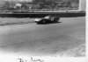
Steering Design, Part II
With the analysis of the front suspension complete, it was time to test the plan.
We needed to measure two parameters. First, the change in camber when the suspension goes up and down and, second, the degree of bump steer.
Camber, or the degree to which the upright tilts in or out, changes as the wheel is moved up and down due to the unequal length of the control arms. Camber has to be plotted as the hub is moved up and down, since bump steer is measured in comparison to it.
In order to determine these measurements we came up with a primitive rig using a laser level, carpenter’s square, car jack, and assorted blocks. Don’t laugh. It worked.


Three blocks were cut to support the control arms at normal, 1 1/8 inch below, and 1 1/8 above normal wheel ride height. Our premise was that this would be enough travel to document the camber and bump steer trends for analysis purposes. The suspension was set at a ride height of five inches, measured from the bottom of the frame below the engine supports.

The laser level was firmly connected to the brake rotor so it would not move. The suspension was now raised and lowered keeping the laser parallel to the center line of the car and the blocks then placed under the control arm at the three different heights. The laser beam was plotted on graph board at these locations. This defined the arc caused by the change in camber.
With the camber plotted, bump steer could now be determined. A straight steering arm was cut from one inch square steel tube for testing purposes. The steering wheel was turned to simulate a two inch extension of the inner tie rod pivot point. The rod end was attached with a number of washers to keep the tie rod parallel with the upper control arm when viewed from the front of the car. The suspension was again moved up and down, but now the wheel was permitted to veer left or right based on the connection to the tie rod and the degree of bump steer. This was plotted on the graph paper over the camber plot.

By changing the number of washers between the rod end and the steering arm the amount of bump steer could be altered. Washers totaling approximately ¾ inch produced a very good result with minimal bump steer. The bump steer was ‘toe in’ slightly at the upper limit of travel. If there is any bump steer, it must be toe in, not toe out.
We copied the final and best result on a sheet of graph paper. The camber and bump steer movement, which is the horizontal component, is better than the graph would suggest. The laser was positioned some four feet away from the poster board, so the left – right motion of both the camber and bump steer is greatly magnified. What is important is that the two lines track reasonably close but the deviation of the bump steer when the wheel is raised is toe-in. This is critical. One strives to minimize bump steer, but if it occurs, it must be toe-in on bounce. Once the final components are fabricated we expect to be able to achieve even better results.
Also noteworthy is that the degree of bump steer is nominal within the 1 1/8 inch above and below the normal ride height. For evaluation sake we jacked up the wheel a couple more inches to see how much deviation we could induce. This obviously increased the bump steer with toe in, but for the reasons noted, this should not be an issue.

With our data in hand, measurements complete, and confirmation of the design, we ordered the parts needed to put the plan together as described in prior posts.
Once parts we have ordered arrive, another option for the steering arm connections will be pursued.
With the analysis of the front suspension complete, it was time to test the plan.
We needed to measure two parameters. First, the change in camber when the suspension goes up and down and, second, the degree of bump steer.
Camber, or the degree to which the upright tilts in or out, changes as the wheel is moved up and down due to the unequal length of the control arms. Camber has to be plotted as the hub is moved up and down, since bump steer is measured in comparison to it.
In order to determine these measurements we came up with a primitive rig using a laser level, carpenter’s square, car jack, and assorted blocks. Don’t laugh. It worked.
Three blocks were cut to support the control arms at normal, 1 1/8 inch below, and 1 1/8 above normal wheel ride height. Our premise was that this would be enough travel to document the camber and bump steer trends for analysis purposes. The suspension was set at a ride height of five inches, measured from the bottom of the frame below the engine supports.
The laser level was firmly connected to the brake rotor so it would not move. The suspension was now raised and lowered keeping the laser parallel to the center line of the car and the blocks then placed under the control arm at the three different heights. The laser beam was plotted on graph board at these locations. This defined the arc caused by the change in camber.
With the camber plotted, bump steer could now be determined. A straight steering arm was cut from one inch square steel tube for testing purposes. The steering wheel was turned to simulate a two inch extension of the inner tie rod pivot point. The rod end was attached with a number of washers to keep the tie rod parallel with the upper control arm when viewed from the front of the car. The suspension was again moved up and down, but now the wheel was permitted to veer left or right based on the connection to the tie rod and the degree of bump steer. This was plotted on the graph paper over the camber plot.
By changing the number of washers between the rod end and the steering arm the amount of bump steer could be altered. Washers totaling approximately ¾ inch produced a very good result with minimal bump steer. The bump steer was ‘toe in’ slightly at the upper limit of travel. If there is any bump steer, it must be toe in, not toe out.
We copied the final and best result on a sheet of graph paper. The camber and bump steer movement, which is the horizontal component, is better than the graph would suggest. The laser was positioned some four feet away from the poster board, so the left – right motion of both the camber and bump steer is greatly magnified. What is important is that the two lines track reasonably close but the deviation of the bump steer when the wheel is raised is toe-in. This is critical. One strives to minimize bump steer, but if it occurs, it must be toe-in on bounce. Once the final components are fabricated we expect to be able to achieve even better results.
Also noteworthy is that the degree of bump steer is nominal within the 1 1/8 inch above and below the normal ride height. For evaluation sake we jacked up the wheel a couple more inches to see how much deviation we could induce. This obviously increased the bump steer with toe in, but for the reasons noted, this should not be an issue.
With our data in hand, measurements complete, and confirmation of the design, we ordered the parts needed to put the plan together as described in prior posts.
Once parts we have ordered arrive, another option for the steering arm connections will be pursued.
Exhaust system, Plans
The original plan was to run the exhaust under the D Type, however this proved impractical. The RCR floor is a couple of inches lower than the original to provide more passenger compartment room. Although this modification is good for the driver and first mate, it would make exhaust pipes under the car too friendly with the pavement. So side exhaust became the most viable option.
The original had details that we wanted to emulate. First is the manner the pipes are suspended: with springs. In this picture the spring between the side pipes support and the body is visible.

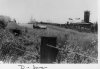
Look very close at the following picture. The location of the springs inside the body can be seen. This suggests that two springs were used on each connection so that the side pipes could move both in and out, centered by the tension of the springs.

Second is the use of flexible pipe between the headers and the side pipes. Although we will not be using original style headers (not likely available these days), the flexible pipes emulate the original and should absorb the motion and vibration between the engine and side pipes better than a rigid connection.

Third is the connection to the side pipes. There is a prominent vertically mounted bolt which can be easily duplicated, visible in the foregoing photo.
With these goals in mind it is time to come up with a plan.
The original plan was to run the exhaust under the D Type, however this proved impractical. The RCR floor is a couple of inches lower than the original to provide more passenger compartment room. Although this modification is good for the driver and first mate, it would make exhaust pipes under the car too friendly with the pavement. So side exhaust became the most viable option.
The original had details that we wanted to emulate. First is the manner the pipes are suspended: with springs. In this picture the spring between the side pipes support and the body is visible.
Look very close at the following picture. The location of the springs inside the body can be seen. This suggests that two springs were used on each connection so that the side pipes could move both in and out, centered by the tension of the springs.
Second is the use of flexible pipe between the headers and the side pipes. Although we will not be using original style headers (not likely available these days), the flexible pipes emulate the original and should absorb the motion and vibration between the engine and side pipes better than a rigid connection.
Third is the connection to the side pipes. There is a prominent vertically mounted bolt which can be easily duplicated, visible in the foregoing photo.
With these goals in mind it is time to come up with a plan.
Similar threads
- Replies
- 1
- Views
- 459
- Replies
- 1
- Views
- 2K