It definetly takes less space behind the bulkhead and could have get away with a smaller bulge if I knew before.


You are using an out of date browser. It may not display this or other websites correctly.
You should upgrade or use an alternative browser.
You should upgrade or use an alternative browser.
Electric water pump and digital controller question
- Thread starter JHeinke
- Start date
I have decided to move in a particular direction and not use AN fittings (not just $$). First I have a lot of 1-1/2" stainless tubing already, I'm going to use as much of that as I can. Another reason is simplicity. The SS tubing and the pump inlet/outlet are 1-1/2". Which for direct fitment of AN weld-on-bunges would be -20AN not -16AN (the davies craig even has an -12AN). Necking down first is certainly possible and there are also -16orb to -20an fittings, but this just seams overkill when there is an easier solution that seems to work.
So silicone couplers it is, and since I'm using them up front with the radiator, it's consistent. These are the fittings I may use for the block. No experience with anhosefittings.com or raceflux, but the are pretty cheap at $15 (that's either good or bad).

I think the $ difference for AN fittings and hose would be @ $350. That's going to go toward the ITB's I just decided to buy lol.
So silicone couplers it is, and since I'm using them up front with the radiator, it's consistent. These are the fittings I may use for the block. No experience with anhosefittings.com or raceflux, but the are pretty cheap at $15 (that's either good or bad).
I think the $ difference for AN fittings and hose would be @ $350. That's going to go toward the ITB's I just decided to buy lol.
I'll also report back if this tool will put a bead in .065 stainless tube since I'll be needing a handfull of them. Supposedly good up to 14 gauge if you go slow. Who came up with the name Jobber Do...lol. Well if it works for $59 I'll be happy.

Demonstration vid
Demonstration vid
I modified a pair of Vice-Grips to do tube-end beading and it worked OK for aluminum tubing if I worked around in very small steps. It looks like this one is modified to add leverage and to be held in a vise so it should work better than mine--- so I ordered one just now. Thanks for the info.
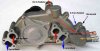
Just got the 417 manifold in and it looks good. In the typical remote manifold setup, two of the -16 ports would be used (1in/1out) and two would be blocked. I am thinking more about my coolant expansion tank now. On the old LS water pump, I had planned to connect the expansion tank to the 3/4" barb heater return. The diagram best describes that.

I was thinking that I would run another barb connection (on the return side of the manifold) to plumb in my expansion tank (3/4" hose). The expansion tank is definitely above the heads, but I'm wondering if the pump is going to blow coolant into the expansion tank. In the above diagram the electric pump is located at 10. The expansion tank would basically be fed by a split at 7 (in that the manifold has two exits).
In the original method, the expansion tank joins at point 10 (pre ls pump), and the pressure is at the lowest point in the system. In the new routing method its in the middle and I'm not sure how that will work.
I think part of the answer is that the expansion tank is pressurized so maybe as long as the pressure doesn't exceed the cap psi rating it's okay. But it doesn't make sense that the expansion tank and overflow might be filled (if that's what would happen). I might have to plumb in a fitting just prior to the pump inlet...at the top of the 1-1/2" tubing (near the end of 9 and 10). Please share you thoughts and experience.
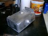
My overflow is as pictured. There is basically a straw that goes to the bottom of the tank, so it will suck back to the expansion tank under the vacuum.Wouldn't it be better to have the inlet to the overflow tank at the bottom? This way the vacuum created when the engine cools down and the radiator cap vent opens, it will suck liquid back into the system rather than air.
here's the post on my build that shows the tank I made.
Howard Jones
Supporter
Everything you ever wanted to know about cooling systems.
I am pretty sure you want the hose that comes from the cooling system to the inlet of the expansion tank to be attached to the lowest PRESSURE point in the system. This will also be the coolest temp coolant and will be the returned coolant from the radiator. On your chart that would be the hose coming from #9 to the pump inlet. Put the fitting on the hose (pipe) BEFORE the inlet to the pump. This is the lowest pressure point in the entire system just ahead of the pump impeller.
None of the ports on this log-type manifold can be used for this because the pump itself is external to the system and therefore its low-pressure inlet is remotely located. As you can see in the above picture of the LS pump you will not be blocking any of the ports on your manifold. All are used to accommodate your pump output to the motor and engine hot coolant return to the radiator.
So, let's start at the radiator cool water outlet: This hose is attached to the pump inlet after traveling down the side pod, and here is where you want to attach your expansion tank main feed. Then the main coolant flow is pumped from the pump outlet to the bottom AN port and bottom half of your manifold in your picture (the one attached to the square ports). The water then flows into the block and back out of the heads (round holes) and back into the top half of your manifold to the top AN port of your manifold. You will then attach this point to the hot side of the radiator after traveling down the other side of the car in the other side pod.
Air bleeds: the idea is to allow all the air in the system to return to the expansion tank. So one must come from the top of the radiator and the other from the top of the engine (heads and best at rear of them). If you install a heater. Then you will need to determine if air is getting trapped in it and if so add a third air bleed line from the top of the heater system to the expansion tank.
Main feed from coolant system to expansion tank: As above it must come from the lowest pressure point in the entire system and this is directly at the inlet face of the pump impeller. Place the main feed in the expansion tank on the bottom so that it is covered with coolant and the small bleed line at the top so that they return into the air at the top of the tank under the radiator cap.
The line to overflow tank: Run a line from the radiator cap blowoff port on the side of the fill neck to the bottom of the overflow tank. The overflow tank must not be pressurized. So a vent needs to be installed at the top of it. I like to do this with a hose that ends at the back of the car BEHIND the tires so that if the coolant comes out of the car it does not end up on the rear tires.
That is the entire coolant system routing.
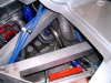
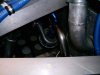
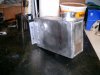
My picture shows you (barely) my main expansion line feed. It's the AN fitting welded onto the tubing that is directly attached to the pump inlet. The other end is the silver steel braided line that goes to the bottom of the expansion tank (square aluminum tank). The pictures of the tank itself show the two bleed line inlets at the top and the bigger bung for the main feed at the bottom.
I am pretty sure you want the hose that comes from the cooling system to the inlet of the expansion tank to be attached to the lowest PRESSURE point in the system. This will also be the coolest temp coolant and will be the returned coolant from the radiator. On your chart that would be the hose coming from #9 to the pump inlet. Put the fitting on the hose (pipe) BEFORE the inlet to the pump. This is the lowest pressure point in the entire system just ahead of the pump impeller.
None of the ports on this log-type manifold can be used for this because the pump itself is external to the system and therefore its low-pressure inlet is remotely located. As you can see in the above picture of the LS pump you will not be blocking any of the ports on your manifold. All are used to accommodate your pump output to the motor and engine hot coolant return to the radiator.
So, let's start at the radiator cool water outlet: This hose is attached to the pump inlet after traveling down the side pod, and here is where you want to attach your expansion tank main feed. Then the main coolant flow is pumped from the pump outlet to the bottom AN port and bottom half of your manifold in your picture (the one attached to the square ports). The water then flows into the block and back out of the heads (round holes) and back into the top half of your manifold to the top AN port of your manifold. You will then attach this point to the hot side of the radiator after traveling down the other side of the car in the other side pod.
Air bleeds: the idea is to allow all the air in the system to return to the expansion tank. So one must come from the top of the radiator and the other from the top of the engine (heads and best at rear of them). If you install a heater. Then you will need to determine if air is getting trapped in it and if so add a third air bleed line from the top of the heater system to the expansion tank.
Main feed from coolant system to expansion tank: As above it must come from the lowest pressure point in the entire system and this is directly at the inlet face of the pump impeller. Place the main feed in the expansion tank on the bottom so that it is covered with coolant and the small bleed line at the top so that they return into the air at the top of the tank under the radiator cap.
The line to overflow tank: Run a line from the radiator cap blowoff port on the side of the fill neck to the bottom of the overflow tank. The overflow tank must not be pressurized. So a vent needs to be installed at the top of it. I like to do this with a hose that ends at the back of the car BEHIND the tires so that if the coolant comes out of the car it does not end up on the rear tires.
That is the entire coolant system routing.
My picture shows you (barely) my main expansion line feed. It's the AN fitting welded onto the tubing that is directly attached to the pump inlet. The other end is the silver steel braided line that goes to the bottom of the expansion tank (square aluminum tank). The pictures of the tank itself show the two bleed line inlets at the top and the bigger bung for the main feed at the bottom.
Attachments
Last edited:
Thanks Howard, that confirms what I had suspected, that I couldn't use the fittings for the expansion tank. What I wasn't sure about, was whether the expansion tank could be plumbed in at the lowest point of the system (pressure wise...Yes). I was kinda thrown off by some instructions from 417 that said the expansion "T" had to be the highest point...I'm sure they meant the tank itself, but was worth confirming anyway. Hopefully I can find some time off to work on it soon.
Howard Jones
Supporter
The "highest point" reference is related to the air in the system having the highest point possible to bleed to. Here we are talking about the air pocket in the top of the expansion tank, where all the return bleed lines are being routed, as being located as high as possible above the water volume. In our mid-engine cars this will be up on the firewall alongside the back window or in the case of an SLC without the window but as high as possible. Every 1/2 inch counts!

Reporting back on the tubing bead roller clampy thing I posted recently. I believe formal name is Jobber-do. Just attaching a picture of the results. This was with about five passes. I know I can put on a more pronounced bead with it, but I think this is sufficient to keep silicone couplers in place. All in all, I'd say worth it.
.065 stainless

Note that tube opening after crimping was slightly smaller by about .07". I can live with that.
Consistent results on about 6 tube ends so far.
.065 stainless
Note that tube opening after crimping was slightly smaller by about .07". I can live with that.
Consistent results on about 6 tube ends so far.
Similar threads
- Replies
- 14
- Views
- 2K
- Replies
- 115
- Views
- 32K
- Replies
- 7
- Views
- 3K
- Replies
- 18
- Views
- 7K