Ford 302 Heating/ Water Flow Configuration

Hi everyone,
Was hoping for a little help..!!. I am struggling to get my cooling system working after realising a few simple mistakes on initial start up and seeing an overheat.

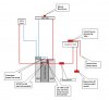
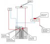
I've looked at all the different threads, but I am getting myself confused with all the different configs, especially those that have a breather run from the main rad back to the expansion tank (which my rad doesn't have at the moment).

I've come up with the following diagram and wondered if anyone could take a look and advise whether this will work. I am concerned that I might be lacking breathers or something else. Any help/ advice great-fully received.

Many thanks,
Rob Girling
 

Attachments

  • GT40 Water Flow Diagram.jpg
    GT40 Water Flow Diagram.jpg
    49.5 KB · Views: 564

Chris Kouba

Supporter
You will need some sort of circulation through the expansion tank. Connect a line from the bottom of expansion tank back to a water pump input port. That should bleed any air out of your system. As it sits now, there is no forced motivation for bubbles to make their way to the tank and purge.
 

Chris Kouba

Supporter
Question I asked:

Lots of theory discussion:
 
Chris is correct. Your header tank is currently a "dead end". And what is the "shut off valve" for? A header tank is an in-line device used to fill the system and needs to have an intake and outlet.
 
Chris/ Lee, many thanks for your replies, that's much appreciated and very helpful. I think what I'll do is re-draw my system as you guys have noted and repost to ensure I have understood correctly. One thing - on my system I just have a bleed screw at the top of my rad, do you think it would be worth modifying this to make it a breather an run a line back to the top of the expansion tank (as per the diagram in the post you attached). Thanks again.
 
Okay, so here is my revised diagram. How does this look?? Thank you.
 

Attachments

  • GT40 Water Flow Diagram - V2.jpg
    GT40 Water Flow Diagram - V2.jpg
    65.9 KB · Views: 391

Chris Kouba

Supporter
I would run the line back from the top of the rad to the expansion tank (and I did, for the record). To simplify things, a spur off the line to the rad may be an easier way to get coolant to the entry of the heater core, but I would run the return to the expansion tank as well (and I did also).

The other recommendation I would have is to get a catch tank for your overflow line. This will let your expansion tank truly do its job and keep any overflow or overheating activities mildly under control. Glycol can make for slippy tires. There are combo units available, which is what I used.

This might be the one I used (if not it's damn close): https://www.summitracing.com/parts/ctr-80-203
 
And here's a good pic of the header tank and house routing from the top of the block to it and the radiator.
 

Attachments

  • Water hose routing.jpg
    Water hose routing.jpg
    61.1 KB · Views: 276
Regardless of everything else, the fitting that screws into the intake manifold behind the thermostat must reach down to the floor of the cooling jacket at that point and have a restrictor ( In factory Ford cars it was a squashed pipe ), this prevents any bubbles in the coolant stream from getting into the heater matrix which would require frequent bleeding.
 
Hi guys, thanks again or the info, I think I'm getting there!! Here's some.pics of my set up, You can see my expansion tank top right. I will see if I can fit some kind of catch tank feeding from the cap outlet. For the heater core I've run some separate 15mm copper pipes from the engine bay down behind the LH fuel tank (my car is RH drive as I'm in the UK) and into the cockpit area so no problem with connections. My pump has one large connection for rad and two 5/8" attachments, so I can connect up rad, heater and bypass okay. Returns come from top of manifold for heater core (note as on the 2nd diagram, it would be easier/ neater for me to connect into the LH side of manifold outlet which is the smaller 3/8 npt fitting rather than 1/2 npt on the RH side - hopefully okay) and off the thermostat for the rad. Note 2nd pic shows incorrect plumping which is where I started (I thought two smaller connectors on pump were originally a send and return for the heater core - it didn't produce good results -doh!!)
IMG_20230411_135448.jpg
IMG_20230423_142815.jpg
 
Regardless of everything else, the fitting that screws into the intake manifold behind the thermostat must reach down to the floor of the cooling jacket at that point and have a restrictor ( In factory Ford cars it was a squashed pipe ), this prevents any bubbles in the coolant stream from getting into the heater matrix which would require frequent bleeding.
Thanks for your post Jac, I've read many a thread on this subject, some say needed and others say not. Laws of physics tell me gas is lighter than water hence this is a possibility if air is in the system). From my practical point of view, it would be good to leave this out, however I am connecting to the smaller 3/8 port on the LH side of the manifold instead of normal position on RH side behind the thermostat which is 1/2 npt. This is something I've been thinking about and not quite got to a satisfactory answer in mind as yet!!. The issue boils down to space around the manifold area and fitting angled connectors will potentially mean removing dizzy, carb or thermostat housing if tapping into RH side. I'm also not sure if there is a stock 3/8 npt version of this fitting, but will take a look. Thanks again.
 
Why would you not tap off the return line from the radiator and run the heater lines into the cabin there. I would not want more water lines running from front to back. More volume to trap air. Did you look at how ERA plumbed their cars in the diagram I sent you?
 
Why would you not tap off the return line from the radiator and run the heater lines into the cabin there. I would not want more water lines running from front to back. More volume to trap air. Did you look at how ERA plumbed their cars in the diagram I sent you?
Hi Lee, it's simply down to logistics. The rad pipes on my car are (large) stainless steel which run through a centre column. The fittings off these at the front are just 90 degree rubbers and then another stainless pipe to the rad. Tapping into the line at this point would be difficult and access in this area is not great. Yes, thank for the ERA diagram that helps a lot. It's a light different config to mine, but that and the other comments has helped understand how the heating system works and where I went wrong, the key one being as you pointed out that my expansion tank was a dead end. In summary I now understand that each component fitted to the water system needs a send and return, which includes the expansion tank. I think.i will alo fitt a catch tank off the expansion tank as Chris noted. Many thanks for your help.
 
One issue I see with the ERA diagram, the heater will do nothing until the Tstat opens. Even then, it's relying on resistance through the radiator for flow.

Far better would be the hot supply off the top of the intake. Returning to the return radiator hose is good to eliminate one pipe, but the dedicated supply will get much better flow and will provide heat long before the Tstat opens enough to give any flow to the as drawn design... unless I'm missing something.
Generally, if the heater is required at all times, we use a separate electric booster from a Mercedes diesel.
 
Back
Top