Homemade CFRP mid engine sports car

Hi all, a few updates

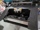
Mostly been fabricating little bits here and there from my big box of carbon fibre fabric offcuts and using up my left over epoxy resin before it goes out of date. The main new thing to share is the pedal box;

PXL_20241101_120548743.jpg

PXL_20241101_120606100.jpg


I need to swap out the accelerator pedal spring with a stiffer one when it arrives, but aside from that its done.

The pedal box will slide along the aluminium rails to adjust position. Ignore the white plastic bars, they are just temporary spacers i printed to hold the rails the correct spacing. The rails will be bonded and bolted to the tub floor.

I made the pedals and frame and footpads from the same process I have shown before .. print a two part mould on the 3D printer, chop up a load of carbon fibre into 50-100mm long strands, mix it with epoxy into the mould .. compress it all over getting all the mould filled (I jab it all over with wooden sticks, add a bit more fibre and resin, then jab some more). Then close the top of the mould and compress the whole thing tightly between clamps, let the excess resin bleed out. The mould needs to be printed quite strong to take the pressure.

my 3d printing booth / spare bedroom toilet, printing a mould for one of the pedals;

PXL_20240924_063141141.MP.jpg

some photos before assembly;
PXL_20241029_201906595.jpgPXL_20241007_201223809.jpg


I've also been making a steering column and i'm about to start making a steering wheel. More on those in a future post !
 
Fantastic build! I just discovered your thread, but will follow with anxious anticipation! Keep the updates coming!
 
thanks guys,

Winter update .. last few weeks i've been manufacturing the steering, designing some brake cooling ducting systems, and shopping for braking system parts and trying to decide on wheel rims.

here's the steering parts. I decided to try and make my own steering wheel, i 3d printed a hollow core for the steering rim, tightly wrapped it in 2 layers of continuous +/-45 degree carbon fibre strip and used spray adhesive to keep it all stuck in place. I used chopped strand carbon fibre (from my large box of offcuts) for the rest. I used a 2 part 3d printed mould, generously added a load of chopped fibre and wet resin onto one side, then added in the wrapped core rim, then a load more chopped fibre on top and then closed the other side of the mould. Then put it in a plastic bag to catch the resin run off and clamp it all tight with as many clamps as i can find. The clamps need to be re-tighted every so often to maintain pressure as the excess resin bleeds out. The demould, sand, paint in a surface coating resin, sand and polish.

PXL_20241118_211838328.jpg


Next was the steering column, in UK IVA you need a system which is collapsible, since my column is short and straight i can't do this via offset multi-link joints, so i needed a collapsible column. I struggled to find one that i liked and was short enough, so i manufactured one from two box section aluminium profiles, with one that slides inside the other. I chose box section rather than round so that even once collapsed it will still steer. I used solid carbon fibre for the rest of the column, moulded directed around and into the aluminium tube. The column is designed to collapse at approx 1kN force via clamp friction from two M5 bolts and i left 90mm of travel.

PXL_20250112_154331874.jpg

PXL_20250112_181528433.jpg


I made an instrument panel beam for steering mounting. The beam is carbon fibre over a 3d printed core, I moulded in two M8 threaded inserts to mount a steering bracket. The steering bracket is moulded from chopped carbon fibre in a 3d printed mould. The only way of adjusting up/down of the column is with a different bracket so i might make a few of these. I need to get a rubber gaiter to seal the column to front bulkhead hole. I'm going to try and print one from rubbery TPU filament.

PXL_20250112_181722674.jpg

PXL_20250112_181849450.jpg

PXL_20250112_181812235.MP.jpg
 
wow two updates in two weeks! this time, ducts for front brake cooling. Made the design in CAD and then 3D printed a multi-part mould, then used a wet layup approach and vac bag. I made it super thin, only 1 ply of 600gsm 0/90 twill and 1 ply of 300gsm +/-45 NCF. Then glued and riveted in place.

The corresponding wheel-side parts were also made today (same process), once cured i'll bond and rivet them to the upright and connect up the hose. Once all done i plan to cover the exposed surfaces near the disk on upright/wishbones/duct with some zircotec self adhesive reflective thermal shield

PXL_20250116_103212981.MP.jpgPXL_20250117_213316800.jpgPXL_20250119_184251533.jpgPXL_20250119_184321515.jpg
 
Bought some more bits in recent weeks, radiator, braking system and wheels (wheels are delayed though waiting on stock, can't wait to test fit those!)

Mounted the radiator on rubber isolators. I've connected bleed lines to the tops of both tanks which T together and then run down the tunnel, I used 3/16 brake lines/hoses for the bleed lines. While messing with the tunnel i also ran a copper cable for earthing front to back (can't ground things to a CFRP body!). I Also made a bracket for the hydraulics reservoirs and fitted them too. Still need to fit the front bulkhead brake/clutch lines and sort hoses inside the cabin to the moving pedalbox.

I have cooling fans arriving this week, once they are test fitted i'm going to mould a CFRP shroud / cooling duct to direct air from the radiator up and out, while also covering/shielding the plumbing on the front bulkhead.

I've also test fitted the brake discs and calipers using some 3d printed placeholder brackets, just to check my maths is correct and everything actually does fit together properly

PXL_20250326_173033924.jpg

PXL_20250326_172951308.jpg

PXL_20250326_173010086.jpg
 

Chris Kouba

Supporter
Paul,

I feel like all I do is fan-boy post on this thread, but I have massive respect for this project and your execution looks phenomenal. This is one of the most interesting threads/projects on this forum for me. Please keep up the efforts and share your progress, I always look forward to the updates! Things are looking great!

Chris
 
Same here. I really appreciate your sharing techniques most people could cobble together in the garage. I really like leveraging 3 D printing to make cores and molds. I got one wanting to use it to make cast aluminum forms.
 
Thanks for the words of encouragement guys, here's the latest updates. Been busy sorting more of the front end out, plumbing the radiator, brake lines, cooling fans and making a shroud for venting the air from the rad. Its a really really tight package in there.

Patiently waiting on the wheels to be delivered, another month yet apparently. I need them to check clearance to the calipers before i commit to making the brake rotor hats or the caliper brackets.

After that i'm not sure what to do next, obviously the powertrain is a rather obvious hole to be filled but might have to wait till next years budget. Maybe make a start on the electric system, lighting etc

PXL_20250412_141523197.jpg


PXL_20250425_192747668.jpg

PXL_20250503_145027536.jpg

PXL_20250503_145131123.jpg

PXL_20250503_145101495.jpg
 

Attachments

  • PXL_20250429_203207237.jpg
    PXL_20250429_203207237.jpg
    504.7 KB · Views: 173
Exciting delivery this week, wheels ! or at least half of them, the fronts are somehow lost in a DHL warehouse somewhere in the midlands, Eurrgh

I decided on APEX SM-10, 19x9 front and 19x11 rear

Test fit on the rears was half successful .. bags of clearance between spokes and calipers so I can repackage the disks further outboard, and I can now get on with manufacture of the rotor hats and caliper brackets. Less good is the distinct lack of clearance between rim and upper wishbone on full droop. However the rims are sitting a little more inboard of the bodywork than expected so I think i'll add in some wheel spacers to get more wishbone clearance, i'd really rather not have to modify/remake those wishbones.

My main activity at the moment is designing some homemade headlights .. nothing to show as yet, just lots of CAD work. More on this in the future


PXL_20250523_142652355.jpg
 
Its been a few months my last post, in that time i've changed jobs so have been a bit distracted from the car project. After more than twenty years of engineering new cars i've now dived into the world of helicopters instead, lots to learn. This car will of course continue :)

I've also been pondering much on powertrain choices, and my primary option at the moment is to buy an old V12 (merc M120, unless something else grabs my eye), recondition it and fabricate some ITBs, then find a tuner to create a map. The most likely transaxle is an audi 01E. This stage will be somewhat scary for me, I stripped and rebuilt an engine and dabbled in engine mapping back in Uni, but that was a very long time ago.

Anyways, current stuff and latest progress .. Two things ongoing, headlamps and brakes fitting.

On the brakes, now i have the wheel rims purchased i've finished the brakes design layout and pushed the disks as far outboard as possible, 10mm more at the front and 30mm more at the rear. I have had rotor hats and brake caliper mounting brackets machined up, and am fine tuning the fitting with some shims.

PXL_20250810_183350127.jpg

PXL_20250810_182926546.jpg

PXL_20250810_183429364.jpg

PXL_20250803_200226792.jpg


Most of the last few months has been spent on the headlamps. Since the car exterior is entirely custom, the lights need to be too really. There are a lot of rules in the UK IVA registration that need to be adhered to so its all been rather complex. I have standard halogen projectors for dipped and main beam (Xenon or LED would need a self cleaning system for IVA), mounted on 3d printed brackets that i can move/rotate around to tune beam aim. The side lights are LED, and the indicators are a string of LED inside a 3d printed translucent block. I opted for a design where the indicators light up in a sequence. I also fitted LED angel eyes around the projectors, not entirely sure how i'll use these yet.
The main casing and lid are CFRP, the lid is designed to be bolt on/off to get to the electrics and for adjustment, i'll seal it with silicone too once all is finished, leaving a small air gap somewhere for condensation. The visible front panel of the lamp is a random placement chopped CF fibre panel, this will be polished up shiny. The lens will be a thin sheet of polycarbonate heated and formed over a mould, then glued on. Then the whole unit will be mounted to the car via three bolted studs, so i can adjust the height and angle of the lamp fitting.

PXL_20250810_183459872.jpg

PXL_20250810_183758283.jpg

PXL_20250720_133144336.jpg

PXL_20250719_144405573.jpg
 
headlamps are on !

PXL_20251015_181246709.jpg


I drape formed some acrylic sheet over a fibreglass former to make the lens's, then bonded them on with primer and adhesive. The dipped headlamps are 'kinda' aligned .. the lamps sit on 3 long bolts so i can precisely adjust both the lamp height and pitch angle to set the beam height. But if i need to adjust it much laterally then i'll need to open the lamps up to reposition the projector, for this reason i've bolted but not sealed the lamp bodies up. Once beams are set i plan to seal them up against water ingress, but leave an air hole to prevent condensation.

PXL_20251005_133429898.jpgPXL_20251005_132906317.jpgPXL_20251012_140338746.jpgPXL_20251015_180324081.MP.jpg

I've started to plan out the fuel tank area. I've plumbed in the nearby cooling pipe routing, the fuel tank will have a cutout to clear these. My fuel system will consist of a custom welded alloy tank (need to decide still whether to get this fabricated somewhere, or to invest in a TIG system and teach myself), with an external low pressure pump feeding a swirl pot, then feeding a high pressure pump. I'm keeping everything external as once the tank is fitted i'll have very limited access to it without taking the engine out.

Any advice guys on pumps ? high pressure i plan to use a bosch 044 equivalent (exact spec depending on engine selection), but i'm kinda unsure on what to use for the external low pressure pump.

Image below shows the fuel tank area, with new coolant lines and header tank & catch pot mounted. The fuel swirl pot will be mounted on the LH side above the sills, the HP pump on the sidewall just underneath it.

PXL_20251015_182032522.jpg
 
truly amazing craftsmanship. It makes me want to start my headlights from scratch, although retrofitting the jaguar ones was hard enough !!!
very impressive work Paul !!!
 
I've been working on the fuel system and the handbrake last few months. I had to sort the handbrake first as the cable needs to run under the fuel tank. I went for an off the shelf handbrake lever but i replaced the handle on it with a cylindrical carbon fibre one (a 3D printed body that has a tight fit over the metal lever end, then covered in chopped CF and squeezed in a 3d printed mould). I made a simple bracket to mount the lever, with some space under to pass gear selector cables in the future. The cables are attached via balance bar to the lever with some rod end bearings.

PXL_20251214_150420328.jpg


I've had an alloy fuel tank fabricated. It has a stiff rubber foam on the front (where it rests up against the cabin bulkhead), and sits on a double layer of said foam, raising it high enough up for handbrake cables and eventual gear change cables to pass under. From a plan view the tank is wedge shaped, this is because to install it you need to drop it into the engine bay and slide it forward, and the engine bay is wedge shaped. I fabricated a wedge shaped CFRP box each side of the tank that bolts to the body structure and keeps the tank wedged into the car. There's around 20mm of free space on the LH side for harnesses to pass through from the battery, which will be in front of the passengers feet, to the rear of the car.

trying to lay out the fuel connections now, as you can see i already have chosen a swirl pot and have mounted it. I will install a lift pump and filter into the bodywork void just behind the swirl pot, on a removable bracket.

The whole fuel tank area will be covered off with a panel, I've purchased a hybrid carbon/kevlar weave cloth for this since this panel will separating the fuel tank from the engine so i'd like some additional toughness.


PXL_20251214_150330223.jpg


Fuel filler added !


PXL_20251212_161238220.jpg
 
Back
Top