Ken's SLC build thread

Joel K

Supporter
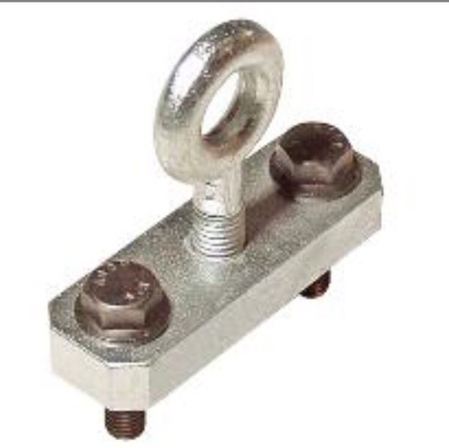
The bearclaw latch is now connected to the outer door handle with a flexible cable. A steel rod connects the bearclaw latch to the inner door handle. The outer door handle lock mechanism works perfectly. No grinding was needed in my application. Not even with the addition of the reinforcing plate at the bearclaw latch. Next up is to buy a couple of momentary "pull" solenoids with remotes. They will connect (in parallel) to the steel rods going to the inner door handles. The outer door handles will remain in the locked position for the most part (similar to shaved door handles)(door poppers won't be needed as I still have outer door handles). The only time I'll need to use the lock cylinder is if the solenoids fail or I lose electrical power. Then it's a matter of unlocking the outer door and using the handle to unlock the door. I wouldn't advice doing this without the outer door lock cylinders operational unless you have an emergency way of activating the latches with a loss of electrical power.
The only problem with this approach is if you leave the door key and door opener fob in the car and close the door. I have keyless starting so for the most part the fob and key will be in my pocket. Please comment if you can think of any problems with this idea!

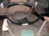
View attachment 103891

Very nice work Ken, I can’t come up with any other recommendations and really like your approach.
 

Ken Roberts

Supporter
The steel rod and plastic end that goes from the bearclaw latch to the Miata inner door handle is in the following link. Drill the hole out in the bearclaw latch to .290" or letter "L" drill.

 
Last edited:

Ken Roberts

Supporter
The braided cable and eyelets I used to attach the bearclaw latch to the outer door handle are mentioned in this link....

 
Last edited:

Ken Roberts

Supporter
The Miata inner door handles are now installed. I copied Dan Carters method of using modeling clay to hold them in the proper orientation before making the three standoffs. The inner door panel can now be removed and installed easily without having to disconnect the linkage.
I was able to use the single steel rod mentioned in post #902. The first picture shows how weak/small the original hole is on the handle. Second pictures shows it ground off and a new hole (.290") placed higher up in the meaty part of the arm. The outer side of the hole gets a slight countersink to capture the barb on the plastic fitting once pushed in.
IMG_3201.JPG
IMG_3203.JPG
 
Last edited:

Ken Roberts

Supporter
The handle is mounted at a complex angle relative to the plate it is mounted to. The front is mounted slightly lower than the plate as shown in the second picture. To aid in mounting the handle to the spacers I bent the three legs at a slight angle (pencil pointing to it in the first picture).

IMG_3209.JPG
IMG_3210.JPG
 
Last edited:

Ken Roberts

Supporter
I'm having second thoughts about installing solenoids in the doors for remote opening. The current draw is 30 amps. Not sure I want to run two 12 gauge wires in my doors. I believe in the "KISS" principle......keep it simple stupid!

It would be a relatively easy install now. The cable pull of the solenoid would just piggy back off the steel rod between the inner door handle and bearclaw latch.
 
Last edited:

Ken Roberts

Supporter
The door handle mounting plate got installed with the use of rivet nuts. Constant in and out during fit up mandated their use. Gotta say....this inner door handle install was one of the most difficult things I've had to fabricate on the SLC to date.

IMG_3212.JPG
 
Nice work Ken. That is one robust setup. My theory in designing industrial machinery has always been “steel is cheap, problems are expensive”. We must have went to the same school of thought.
 
...The current draw is 30 amps. Not sure I want to run two 12 gauge wires in my doors...

You can get by with lighter wire, especially since it is momentary usage. Assuming 30A, 13.8v and 8 feet of wire, you would see 12.8v with 16ga, 13.2 with 14ga.

Not the kind of voltage drop you would want on a fuel pump. But for this usage it's probably a non-issue.
 

Ken Roberts

Supporter
In preparation for installing the body for the last time I copied A.J. Schreder's use of leveling mounts to aid in getting the rear of the spider to match the upper door heights. The first picture is borrowed from his build log. I had to make one bracket shorter than the other due to my coolant tank mounting in the same area.
The leveling mounts are available here....

2015-08-29_01.jpg
IMG_3227.JPG
 
Last edited:

Johan

Supporter
In preparation for installing the body for the last time I copied A.J. Schreder's use of leveling mounts to aid in getting the rear of the spider to match the upper door heights. The first picture is borrowed from his build log. I had to make one bracket shorter than the other due to my coolant tank mounting in the same area.
The leveling mounts are available here....

View attachment 104179View attachment 104180
Ken just think about fiberglass is a living material, it doesn’t like static pressure. Put a half full beercan on the rooftop and you will have a noticeable indent after 6 months.
I would make some kind of reinforcement on the body to spread the load before you put any pressure on the leveling mounths. It could easy be 10 psi static on that spot.
 

Ken Roberts

Supporter
Here is a template for making a Graziano transaxle lifting tool. This tool replicates the OEM tool shown in the EBay link.

Remember to set your printer to 100%. Drill the two outer holes with a letter P drill (21/64" will also work but be a little looser). Drill the center hole for the lifting eyelet to 27/64" and tap the hole with a 1/2" -13 "coarse tap". Use a steel plate that is at a minimum 3/8" thickness (mine is 3/8"). Note in the first picture that the threaded part of the eyelet can't protrude too far past the bottom of the plate due to interference with the webbing in the transaxle. The 2 mounting bolts are M8x1.25mm x 20.
The eyelet is this one......


IMG_2459.JPG
IMG_2461.JPG
 

Attachments

  • lifting plate.pdf
    1 MB · Views: 255
Last edited:

Johan

Supporter
Heads up display buttons were installed in the passenger door panel. These were originally installed on the side of the gauge cluster in the C6 Corvette. I had no room to mount them like that and once you set it you hardly ever touch it again. View attachment 104279
Ken, do you have the approximate measurements and depth of the pull down handles.
 

Ken Roberts

Supporter
Last edited:

Howard Jones

Supporter
Have a look at my build thread post #425. These flanges really stiffen up the center section and allow it to be bolted onto the upper firewall sheet metal behind the seats.
 

Attachments

  • HPIM1434.jpg
    HPIM1434.jpg
    181.1 KB · Views: 340
Back
Top