LS crate motor wiring harness modifications

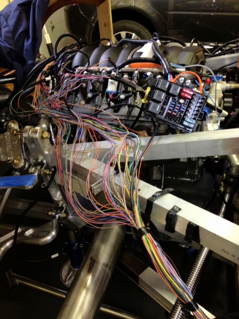
Let me start by saying that I am somewhat disadvantaged as my crate motor and harness are at RCR; therefore, I dont have anything to lay out and see what needs to be extended/modified, but I have read enough build threads where people have mentioned having to cut into their harness and splice in extentions :thumbsdown:

I then happended upon this thread where a company makes an extension for the GM pedal/throttle by wire system :thumbsup:

http://www.gt40s.com/forum/slc-clubhouse/38418-etc-extension-cable.html

So... this got me thinking... for a guy who wants to get ahead of the game, save some time, save some aggrivation, maintain reliability & longevity of the factory harness... maybe they make all the required extensions for the reversed intake manifold? So... I called Current Performance but was unable to get a technical guy on the phone. I am on the call back list though :sleep:

Anyway... so here is my question to all of you... is there a company that makes "all the required electrical extensions" so a guy doesnt have to perform surgery on their harness?

Thanx.


KV
 
Kevin,

I will gladly send you the harness/ecu if you would like to have something to fondle during the cold Canadian nights....
 
Thanx Fran... but for it to truly be of use I would need the motor to go along with it... which would create a different problem.

I am hoping:

1) There is a company out there who already supplies the required extensions, or

2) I can get a list of the circuits that require extensions and I can approach a company like Current Performance to make up some extentions.

Thoughts?


KV
 
You may be over-worrying on this. I don't think anyone has had to extend anything except the ETC, which has already been discussed.

Some builders have re-done the harness entirely by shortening wires where they might be a little long, but the vast majority of cars just manage with the stock wire lengths in the harness. Even the 01 car had excess harness length looped neatly instead of cutting it up.

Builders using the LS-series engines probably don't know how good they have it, compared to the alternative of making up a new custom harness from scratch, especially for engines that are not widely understood. For example, if you were putting an F-car engine in your car as one builder is doing, I would imagine that wiring would be a pretty intense, expensive proposition. With the GMPP harness, it's about as simple as it could be- everything is there, and labeled.
 
Hmmm... I will have to go back a re-read a few threads. I was certain people were pulling apart their harnesses and soldering in sections.

I hope I am wrong and you are right :thumbsup:
 
People are making this too hard.

Step 1 - cut open harness loom

Step 2 - pull out DBW wires

Step 3 - re-loom it out

Step 4 -Done

The only way the DBW won't reach the pedals is if you put the damn thing at the verrrrry back of the car. With mine located on the upper frame rail towards the center-rear of the car, I had to loop the harness undernaeth my seat. Way too much bloody wire to use.
 
Hi Alex... thanx for chiming in.

Just so I am 110% clear... if a person:

1) Utilized a DBW extension... there would be no reason to open up the harness and modify it in anyway?

2) Didn't utilize a DBW extension... the only reason to open the harness up would be to pull out additional existing DBW wire?

I'm going to have to go and find that thread (and post it) where someone had done some reasonably major surgery to their harness (i.e. reversed intake manifold changes locations of some things).

Anyway... cant wait to come over and see your SLC. I'm flying down to Nevada for some track time this weekend... but anytime after that would be great.

Thanx broski!


KV
 
Ha! Found it... In order to protect the innocent (and not get myself in trouble) I wont include a link as this particular build thread is not on this site... but I shall include a quote and a picture :thumbsup:

"In short order I discovered that, in its current configuration, the GM wiring harness wasn't going to work out well. Part of the issue, aside from obviously not being installed in a Corvette, is that the intake manifold is reversed. This is done purely for clearance issues. The fuel rail also gets flipped around, and the wiring harness comes from the "front" of the engine as opposed to the rear as intended. To sum this up; wires aren't where they should be, so I had to tear the harness open from stem to stern"

 
Anyway... if the only issue is the length of the DBW... that is awesome and this can indeed be laid to rest :thumbsup:
 
Opening the harness up isn't rocket science (got scissors, lol)

I wasted like 7hrs trying to use the harness as provided. Beyond the DBW issue, I just wasn't happy with the routing of some of the wires (e.g., knock sensors came way too close to headers for my liking, etc...) so I opened it up and re-routed everything to my specification, then loomed it back up with high temp nylon loom and havn't looked back.

I'd be far more worried about the Mexicans who assemble it messing up the pins - I've read horror stories on LS1tech about people getting harnesses where one or two pins were not installed in the right spot and they spent hours with an ohm meter (or whatever tool they used) in order to figure out which were the problem pins.
 
There is no need to tear apart the harness....imho

We never have and we use an ETC jumper harness to reach the pedal....

If you're obsessive compulsive and want to run things your way there is, haha :D

Needless to say, this image describes to me a T :laugh:

inspiration-unique-fork.jpg
 
"In short order I discovered that, in its current configuration, the GM wiring harness wasn't going to work out well. Part of the issue, aside from obviously not being installed in a Corvette, is that the intake manifold is reversed. This is done purely for clearance issues. The fuel rail also gets flipped around, and the wiring harness comes from the "front" of the engine as opposed to the rear as intended. To sum this up; wires aren't where they should be, so I had to tear the harness open from stem to stern"

Just quoting the text is enough to find the site, in the first 7 words. Google knows EVERYTHING.
 
Here is what I did. Prior to this, I had NO experience with car/engine wiring.

I made it difficult on myself by thinking it was complicated. It just isn’t. It is deceptively easy – no cutting/soldering/extensions needed. The GM guys have made this as idiot proof as possible and all the connections are labeled/unique so you REALLY have to work if you want to screw it up….which of course I was able to do, but read on and you will see how easy it was to correct my screwup.

I took my harness apart while sitting on the floor of my office expecting to simply pull out the extra DBW length I needed – and in the process, got confused about what went where and spent hours trying to re-loom/wrap things back up. Wires were wrapped back onto themselves, mixed up in weird ways I didn’t expect, multiple wires connected onto a single wire back to the ECU…what a mess. So I did get the DBW out and harness wrapped back up but it looked like pretty ugly.

Once I had the engine in, all the connections made, (and engine running!) I realized (like Alex) it worked but I wanted a cleaner look and the ability to route wires away from chafing/heat. I got out the scissors and cut off all the loom/electrical tape. It looked like rats attacked my engine compartment. (see picture)

I then started one connector at a time, one wire at a time. I pulled the wire out of the plug, snaked it out of the messy bundle and all the way back to the ECU connector. Then I re-routed the wire back to the connector/installed it back in. In order to make sure I didn’t introduce any problems, I finished each work session with a test to make sure the engine started/ran. That way, I would only have to review the work I did that session instead of troubleshooting the whole harness if there was a problem.

I use blue painters tape to temporarily hold wires together/where I wanted them because pulling off electrical tape is a pain in the butt. You will change your mind about where things get routed as you go through the harness. As Will stated, simply run the wires with excess length back onto themselves and once everything is closed up you will never know there are wires longer than needed.

Once I had everything done, I knew what size loom to get, in what lengths, and where I wanted heat shielding. I replaced the temp blue tape with electrical tape, and installed the finish loom/heat shield for the final fit. It looks like a custom harness.

Probably the most difficult thing was figuring out how to remove a pin from a connector. There are some slight difference between some of the plugs. Send me a PM if you need me to explain it. Once you get the concept, it is easy to figure out when you run into a different plug.
 

Attachments

  • clean up.jpg
    clean up.jpg
    15.3 KB · Views: 394
Awesome... thanx Peter.

I look at the way I am going to build my SLC (rather basic track only build) and I just dont see the complexity in it (assuming the right parts go in to start with).

At the same time... I dont want to get cocky and assume I will have it built in 120hrs... so I am trying to seek out that "unanticipated thing" that will eat my lunch and add unwanted time to the build. I thought the LS harness was gonna be one of those things... thankfully I was wrong.

Anyway... thanx for the info and reminder in not making things harder than they have to be.


KV
 
Back
Top