
- Forums
- GT40 Replica Manufacturers' Corner
- RCR Forum - RCR40/SLC/917/Superlite Aero
- The SLC Clubhouse
You are using an out of date browser. It may not display this or other websites correctly.
You should upgrade or use an alternative browser.
You should upgrade or use an alternative browser.
Mark's GT-R Build
- Thread starter mksetter
- Start date

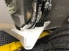
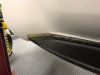
With the aluminum trimmed, I mounted the splitter on the under pan and fine trimmed the body by rotating the splitter up, making sure it was level, and marking on the body were the fine trimming was needed. At first it need quite a bit, but after an hour or two, I am now down to within an 1/8th of an inch to having a good fit between the body and the splitter. Should have it finished tomorrow.
Attachments
Steve, if I can do it, anyone can do it. Measure three times, cut once.
Ron McCall
Supporter
Mark,
Nicely done. Make sure that you build in a bit of rake to the splitter . ( You want it to be roughly 3/4" higher at the very front than the chassis level) That way the splitter is level at ride height when the car has a slight amount of front down rake.
Ron
Nicely done. Make sure that you build in a bit of rake to the splitter . ( You want it to be roughly 3/4" higher at the very front than the chassis level) That way the splitter is level at ride height when the car has a slight amount of front down rake.
Ron
Thanks Ron. I will put the car back on the ground, adjust the suspension, then do the finish work on the splitter fit. As you know, this is really an important modification to get right. Thanks for keeping an eye on me.
Not much to show today. I followed Ron's advice and started getting a completely aligned body, with suspension ride height, before doing the final fitting on the splitter. I had the body alignment "eyeballed" before, but now I want to see it at "finish fit" before going any further with the splitter. It may be a few days.
I have been following Ron's advice and re-installing the body to get the alignment set, then setting the ride height. It was great advice.
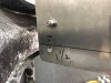
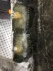
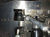
Anyone that has a GT-R knows the difficulty in bolting together the rocker panel and the vertical body panel at the back of the door opening. There are two hidden bolts that have near zero access. I am certain Fran had no choice in the location of these fasteners, because this area requires excellent attachments due to the door lock being in this area. To make the task of getting these bolts in their proper positions and fastened, I ran the bolts threads up thru the rocker, then fiber glassed them in place. This really facilitated their being easier to work with.
Anyone that has a GT-R knows the difficulty in bolting together the rocker panel and the vertical body panel at the back of the door opening. There are two hidden bolts that have near zero access. I am certain Fran had no choice in the location of these fasteners, because this area requires excellent attachments due to the door lock being in this area. To make the task of getting these bolts in their proper positions and fastened, I ran the bolts threads up thru the rocker, then fiber glassed them in place. This really facilitated their being easier to work with.
Attachments
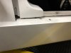
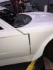
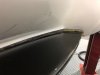
The body was really aligned well from RCR, so I assumed that things would line up well when I put the body back together. Most of it looked great. A few areas needed a few extra washers to get it right. I don't know how it happened, but the front was way off. Somehow the entire front section ahead of the windshield lowered, making the seam in front of the door really wide. Again, I would not have appreciated this degree of shift if I had not remounted everything. Next, I will re-mount the front body supports, then adjust the ride height, then finish the splitter modification.
Attachments
Looks like you're coming along great Mark.
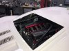
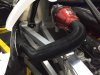
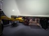
The other really cool thing about putting the entire body together is that it allowed me to finally see what the motor would look like through the back window.
That intake looks great! Other then a set of individual intakes/stacks I don’t think you can get more attractive then that set-up.
Before deciding on this intake setup, I looked into doing individual stacks, but my engine builder, Katech, said that if I decided to do that, I would need to give up all of the benefits of computer controlled engine management, and significant horsepower. Stacks look terrific and they have the historic aspect to them, but they can be difficult to get working with engine management.
Before deciding on this intake setup, I looked into doing individual stacks, but my engine builder, Katech, said that if I decided to do that, I would need to give up all of the benefits of computer controlled engine management, and significant horsepower. Stacks look terrific and they have the historic aspect to them, but they can be difficult to get working with engine management.
Yes your set up has "function and fashion". Where do you plan to run your intakes?
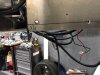
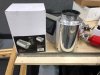
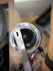
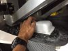
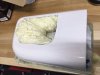
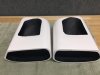
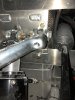
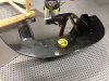
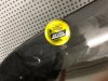
I made some fiber glass "collectors" for the side scoops that are behind the doors. Per Ken's suggestion, I am having 4" tubing run thru Spectre Performance aluminum air cleaners, up to the throttle bodies on each side. The tubing will be powder coated with a wrinkle finish black surface just like the tubing running from the throttle bodies to the carbon intake. I want to make use of the "Ram Air" affect that Robertson Racing used. In the movie Ford GT an American Icon, Robertson himself spoke of the big advantage the "Ram Air" affect the side scoops provided. The tubing will start out as polished aluminum, and it is large diameter stuff, but I want the tubing more subtle so I am powder coating it wrinkle black.
I wanted to add the photos of the air collectors that I made when I first started the car, but as you can see in those photos, the air cleaner I was using was a small diameter K and N unit. Thankfully Ken and some others questioned the air flow with those filters. After some research, I found the Spectre air cleaners that I will be using. They have the same internal design as the K&N, but way larger diameter.
Attachments
-
 IMG_5478.jpg49 KB · Views: 528
 -
 IMG_5479.jpg50 KB · Views: 479
 -
 IMG_5480.jpg38.8 KB · Views: 473
 -
 Air Collector Temporarily Attached.JPG109.6 KB · Views: 534
 -
 Collector Location Inside Body Scoop.JPG101.8 KB · Views: 466
 -
 Air Collector Mold.JPG84.6 KB · Views: 469
 -
 Added to Initial Mold.JPG79.4 KB · Views: 477
 -
 Fiberglass Air Collector.JPG75.5 KB · Views: 472
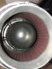
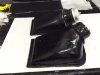
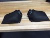
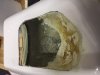
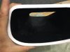
When I made the air collectors, I also modified the side scoops to get better air flow. Turbulence is the enemy of flow, so I made the inside of the scoops like a water slide. When I add the 4 inch tubing between the scoop/collector and the throttle bodies, the air flow should help the horsepower, especially at speed.
Attachments
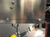
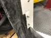
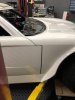
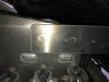
When I got the front end lined up, I had to remount the aluminum body supports to maintain the new body position. You can see from the top row holes the degree it was off. Fran made it easy to correct this by having a lower set of holes in the body support bracket. I just drilled and tapped new holes in the lower row, then "ovalized" the upper hole to make it match the new position.
Attachments
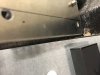
With the body mounted properly, I went back to my pivoting the splitter off the front of the floor pan and more body modification was needed, both on the fiber glass and the lower edge of the aluminum body support brackets.
Then came the error...... A big one!
Then came the error...... A big one!
Attachments
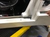
When I was pivoting the splitter, I intentionally did not tighten the bolts holding the splitter to the front of the aluminum floor pan so that when I pivoted the splitter I did not break the splitter gel coat.
The problem is that when I got down to the last little bit of body modification, and I did tighten the bolts attaching the splitter to the floor pan, the splitter changed position and was pivoting from a different, more correct point. That made my cuts to the body WAY OFF!!. Too much body removed from the back area that was trimmed.
If I have learned anything about this build it is taking any problem and saying "I will figure it out." So......
Attachments
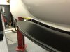
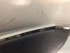
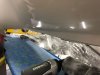
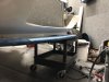
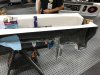
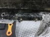
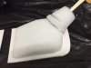
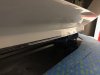
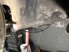
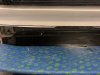
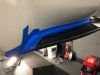
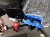
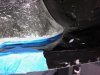
I previously ordered some vinyl ester resin for body repairs, so I put some heavy coats of mold release on the splitter, then mounted it precisely, leveling the body on the hoist, then leveling the splitter to the body, drilling the mounting brackets and tightening all of the splitter attachment points. I blocked out with tape, then glassed in the gap between the body and the splitter. After a few layers had been laid down and cured, I separated out the splitter and used body filler to smooth the junctions.
I have yet to determine the finish lines at each end where the splitter end at the wheel well. That is the final step before mounting the splitter again, for good.
I have yet to determine the finish lines at each end where the splitter end at the wheel well. That is the final step before mounting the splitter again, for good.
Attachments
-
 IMG_5481.jpg75.7 KB · Views: 468
 -
 IMG_5482.jpg49.2 KB · Views: 405
 -
 IMG_5493.jpg38.3 KB · Views: 430
 -
 IMG_5494.jpg34.5 KB · Views: 419
 -
 IMG_5491.jpg61.5 KB · Views: 399
 -
 IMG_5495.jpg54.7 KB · Views: 397
 -
 IMG_5496.jpg38.5 KB · Views: 457
 -
 IMG_5497.jpg26.2 KB · Views: 449
 -
 IMG_5499.jpg41.6 KB · Views: 418
Similar threads
- Replies
- 3
- Views
- 2K
- Replies
- 9
- Views
- 809
- Replies
- 5
- Views
- 941
- Replies
- 63
- Views
- 6K