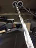
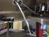
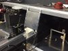
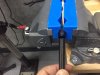
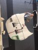
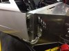
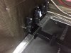
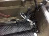
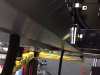
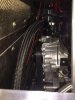
I worked on a number of details most of the day, polishing brackets and making hose connections. The one thing that is visible is I put heat shielding on the front portion of the shifter cables. As you can see, I used a double layer. It may be overkill, but it would be a major PITA to have to change these out after the interior gets finished.

- Forums
- GT40 Replica Manufacturers' Corner
- RCR Forum - RCR40/SLC/917/Superlite Aero
- The SLC Clubhouse
You are using an out of date browser. It may not display this or other websites correctly.
You should upgrade or use an alternative browser.
You should upgrade or use an alternative browser.
Mark's GT-R Build
- Thread starter mksetter
- Start date
Frank Clark
Supporter
On the SLC, the provided cables (at least what I got), were not long enough to route like that. They end up within a couple of inches of the exhaust (with LS7 manifolds), for several inches. I did go with a heavier heat wrap than that (more insulation). But it looks like your cables will not be near the exhaust.
Looks good!
Looks good!
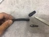
I got lucky in getting cables long enough to go wide of the exhaust system. Some other GT-R appear to have slightly shorter cables. Now I am working on lubricating them to get as smooth a shift as possible.
I am expecting to get the interior tub soon, and want to make sure everything in the interior that can get done is done, so I am finishing the center console face plate and trim. I would like to use this surface to mount the entertainment system and ideally an additional A/C outlet. If I can find a rear view camera that uses the mirror mount, that would be preferred. If I cannot find a mirror mounting monitor, I can use the center console area.
Attachments
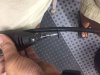
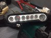
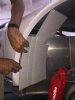
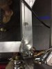
I am getting sore hands from assembling the -4AN fittings for the steam venting system. I am using electrical tape on both sides of the area to be cut, then using a separating disk on a dremmel. This seems to make a nice clean cut. I then use scissors to trim any loose nylon fibers and a countersink drill just rotating it in my fingers with the tip up in the hose opening, with the opening facing down to let the shavings drop. This gets rid of the flash in the hole and has helped make the hose end fitting easier to assemble. Notice I said easier. That does not mean easy. Using a vise, I can get these things together, but the steam system has 10 hose ends by the time I am done.
Attachments
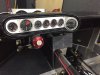
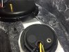
In mounting the gauge cluster to the fiberglass dash, I am using hex headed screws, with the washers and nuts being attached to the inside of the dash with JB Weld. I used heavy grease on the screw threads before applying the adhesive. I will find out tomorrow if I can get the screws out.
Attachments
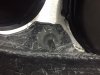
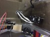
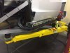
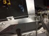
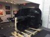
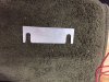
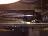
I needed to make some measurements with the front end of the car put in place, so we lowered it from the loft, positioned it on the car and placed some cardboard to simulate the future wheel well liners and marked off the tub. I also wanted to get an idea of how much space there was between the radiator and the front end. Amazingly, there is 1 1/8 inch space along the entire top of the radiator. I wanted to get this in preparation for blocking this out to limit air flow bypassing the radiator. Looks like I can solve that with some rubber molding.
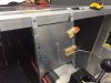
I am running the A/C lines and need to go along the rocker panel area because my tunnel is full. With the wheel well marked, I can safely run the lines up the tub behind the wheel well. I worked on finishing the lines under the dash, but have more time needed to finish that.
I am running the A/C lines and need to go along the rocker panel area because my tunnel is full. With the wheel well marked, I can safely run the lines up the tub behind the wheel well. I worked on finishing the lines under the dash, but have more time needed to finish that.
Attachments
Great job on your build! I noticed your struggle with the AN lines. Have you tried Koul Tools? It might make assembling the fittings easier.
A.J.
A.J.
Great Suggestion, AJ. Most of the AN stuff I have been fine with, but the -4AN stuff has been a bit of a struggle. Thanks for the suggestion.
just buy an AN hose cutter. Snip snip done.
https://www.summitracing.com/int/parts/sum-900040/overview/
https://www.summitracing.com/int/parts/sum-900040/overview/
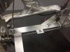
My very good friend from Michigan, Dr. Jim Fraser, joined me for a few days in my shop. Jim is a master car builder, specializing in resto-mod Corvettes, GTO's and Firebirds. I have been getting ready for him to join me for a few days because I wanted to have a few big steps in mind while he was here. I have been working on the brakes, but wanted help with the final steps. We finished the brake lines, bled the system and tested. I wanted to get this done before the motor went in because there are a few key connections in the brake system that are hidden by the motor. I don't want to have to remove the motor to fix a brake line issue.
Jim is a meticulous dentist and car builder, so the brake lines had to look good as well as work good.
When we tested the system, no leaks anywhere under full brake pressure. Awesome!
Jim is a meticulous dentist and car builder, so the brake lines had to look good as well as work good.
When we tested the system, no leaks anywhere under full brake pressure. Awesome!
Attachments
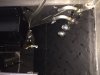
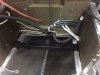
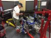
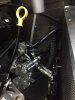
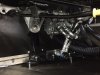
With the brakes tested, I had to remove the remote mounted coils, then did a try-in of the motor to get the exact position for the motor mount cross beam. The motor was removed and the frame drilled for the mount beam. Care was taken to make sure the hole was no larger than needed to minimize any "play" and the position of the hole had to assure that the load was delivered to the frame and not just to the mounting bolt.
This is my friend Jim, who made this easy. This is a step where experience counts.
This is my friend Jim, who made this easy. This is a step where experience counts.
Attachments

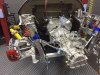
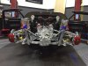
It was amazing to see, after the motor was attached at the adapter plate, the mounting cross beam was perfectly centered on the frame rails. The mounting beam attachment width is slightly wider than the frame rails, so I made four spacer plates that could be slid into place with the bolts in place before they were tightened. I thought there might be the need to "Shim" the cross beam, but the spacers ended up being used to facilitate the bolt tightening. The photos were taken before any spacer plates and with one spacer plate, before bolt tightening.
Attachments
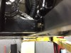
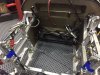
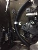
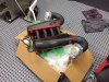
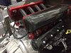
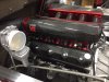
With the motor in for the final (I hope) time, the heater hoses, A/C lines and the coolant hoses were attached. You can see the AN20 line that was used for the water pump outlet. A stainless bung was welded to the coolant tube that comes thru the tunnel.
Attachments
Moving along like a pro :thumbsup:
Great feeling having the motor go in for the first time, congrats!
Thanks for following the build and I really appreciate your comments.
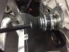
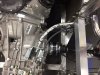
I want to thank Fran at RCR so many times as I am building this car. For me, he has provided the perfect combination of quality components, but leaves enough undone to make you earn the completion of each step. The axles are awesome! Great fit, heavy duty, look great. I did not have enough bolts to complete the installation, but Kristin at RCR contacted the supplier and more bolts are on the way.
I want to thank Fran at RCR so many times as I am building this car. For me, he has provided the perfect combination of quality components, but leaves enough undone to make you earn the completion of each step. The axles are awesome! Great fit, heavy duty, look great. I did not have enough bolts to complete the installation, but Kristin at RCR contacted the supplier and more bolts are on the way.
Attachments
Mark
My engine mount from RCR came (for my SL-C) with U spacers that boxed in the frame rail and provided the correct spacing and support for the mount. You might want to check with Fran to see if that is also true for the setup for the GT-R.
My engine mount from RCR came (for my SL-C) with U spacers that boxed in the frame rail and provided the correct spacing and support for the mount. You might want to check with Fran to see if that is also true for the setup for the GT-R.
Similar threads
- Replies
- 3
- Views
- 2K
- Replies
- 9
- Views
- 809
- Replies
- 5
- Views
- 941
- Replies
- 63
- Views
- 6K