Mark's GT-R Build

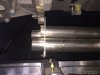
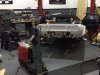
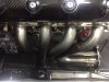
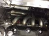
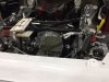
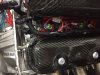
I am getting ready to leave on a motor home trip for a month, but the car will not sit with nothing being done. The guys at Mannix Automotive, next door to my shop, are going to design and build the exhaust system. They have the tooling to do mandrel bending and all types of welding, with argon gas for welding stainless.

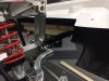
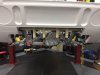
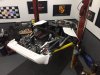
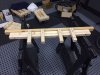
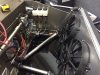
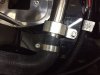
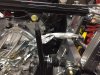
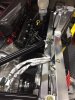
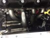
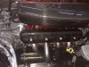
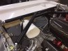
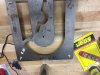
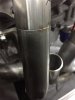
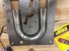
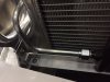
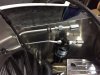
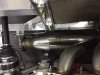
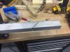
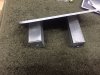
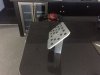
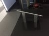
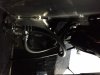
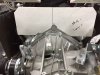
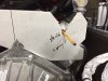
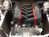
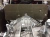
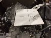
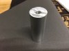
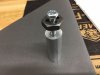
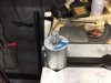
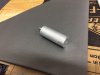
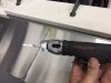
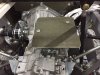
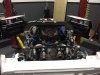
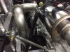
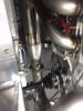
To give them some guidelines, I mounted the rear body support framework, then added the rear body panel. With that in place, I made a jig that would identify the position of the exhaust tips. In mocking this up, I decided that 4 inch tips would look the best, and the position was laid out and located via the framework.

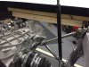
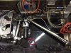
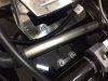
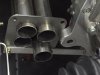
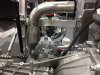
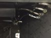
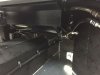
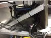
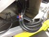
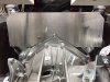
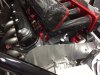
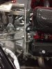
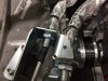
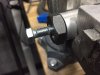
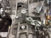
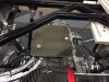
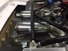
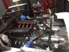
Steve, from Mannix, looked it over and we discussed the routing of the pipes to leave some room for the shifter cables. Had to get all of the questions answered before I leave in a few days.
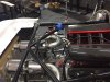
 

Attachments

  • IMG_3853.JPG
    IMG_3853.JPG
    75.6 KB · Views: 535
  • IMG_3855.JPG
    IMG_3855.JPG
    80.4 KB · Views: 556
  • IMG_3856.JPG
    IMG_3856.JPG
    65.2 KB · Views: 549
  • IMG_3854.JPG
    IMG_3854.JPG
    63.6 KB · Views: 618
  • IMG_3857.JPG
    IMG_3857.JPG
    79.4 KB · Views: 728

Ron McCall

Supporter
Mark,


Your car is really progressing nicely. That intake manifold is sweet!
I noticed your exhaust jig pictures and wanted to let you know that I am having some rear bumpers made up in fiberglass for the GT-R. IMHO,
it makes the rear of the car look much more finished and the tailpipes lay out nicer after making the hard turn around the rear of the Graziano. The bumper will look exactly like the production GT bumper except that the top has been extended so that there is not a giant gap between the bumper and the car.
Shoot me an email if you are interested. [email protected]

Ron
 
Previously I outlined the coolant lines from the radiator to the tunnel. Now it is time to actually install them. RCR supplied some shorter stainless tubing to be used for this area, which worked great. They just needed a little polishing to bring out their best. It was amazing how a rag wheel and some white rouge can turn dull into great.

I found some billet clamps that add to the look.
 

Attachments

  • IMG_3543.JPG
    IMG_3543.JPG
    83 KB · Views: 527
  • IMG_3858.JPG
    IMG_3858.JPG
    67.4 KB · Views: 488
  • IMG_3862.JPG
    IMG_3862.JPG
    57.2 KB · Views: 439
  • IMG_3861.JPG
    IMG_3861.JPG
    96.3 KB · Views: 448
  • IMG_3863.JPG
    IMG_3863.JPG
    90.8 KB · Views: 510
  • IMG_3864.JPG
    IMG_3864.JPG
    60.7 KB · Views: 480
I also finished up the installation of the shifter cables by adding a double layer of heat shield to the areas exposed to the engine area.

I also moved them up as high as possible to make room for the headers that are going to be fabricated.

I will be gone for a month but hope to report that the headers are done when I get back.
 

Attachments

  • IMG_3865.JPG
    IMG_3865.JPG
    92.2 KB · Views: 565
  • IMG_3866.jpg
    IMG_3866.jpg
    108.3 KB · Views: 513
Thought I might share some info with you regarding ECU inputs as I just learned this about my own. I'm using Haltech but I'm sure the same for Dominator. Because of the danger involved in DBW throttle body, the inputs from these devices in aftermarket ECU's are redundant, meaning it does the same thing twice and in doing so uses double the inputs. So pedal angle sensor x2, TPS x2 etc. As it is, a normal DBW will take up 4 inputs I think. With two TB's I thought I'd warn you to plan your inputs accordingly as you only have so many digital, analog, temp etc inputs. Sometimes they can be expanded.
 
Last edited:
Thanks for the warning Scott. I have just started looking at the wiring for the motor, and i have yet to lay it out. Mixing manufacturers can make it confusing. Any help is appreciated.
 
I returned from the Smokey Mountains on the motor home and stopped by to see how the headers were coming. They are designed up to the point of attaching the collector and the mufflers were mocked up in paper where I want them. What is done looks great. Now to get it completed.

I look forward to getting back in the shop in a few days and finishing the A/C plumbing, the hose attachments to the motor and to start taking things out of the interior to get the interior tub try-in.

I am really serious about switching to the Audi R8 shifter assembly and will need to pull the trigger on that, since the interior tub needs to go in.

Getting the motor in has opened up so many things that need attention. It is great to have a number of things to design and assemble.
 

Attachments

  • IMG_3988.JPG
    IMG_3988.JPG
    62.2 KB · Views: 505
  • IMG_3991.JPG
    IMG_3991.JPG
    101.7 KB · Views: 478
  • IMG_3992.JPG
    IMG_3992.JPG
    47.9 KB · Views: 484
  • IMG_3993.JPG
    IMG_3993.JPG
    83.4 KB · Views: 490
Steve, from Mannix Automotive, continues on the exhaust build. He moved in with his band saw, belt sander and TIG welder and is able to do his thing right in my shop. Great for me because the fit is perfect and I get to have some input as the system develops.

Great for him because he gets to work with the A/C running and the Big Ass Fan blowing.

He ordered a radius cut jig that he says saves him a ton of time. He has built numerous exhaust header systems, but none with as many variable as this one. As well, he has a jig for the exhaust collector that keeps the pipes in perfect alignment for the collector to easily fit.
 

Attachments

  • IMG_4003.JPG
    IMG_4003.JPG
    87.6 KB · Views: 513
  • IMG_4002.JPG
    IMG_4002.JPG
    89.9 KB · Views: 480
  • IMG_3999.jpg
    IMG_3999.jpg
    60 KB · Views: 506
  • IMG_3998.JPG
    IMG_3998.JPG
    44.8 KB · Views: 544
  • IMG_4004.JPG
    IMG_4004.JPG
    84 KB · Views: 578
While Steve worked on the exhaust system, I worked on the other end of the car, getting the A/C plumbing done. I elected to go with hard tubes right out of the condenser, so I shaped those and attached the dryer.

I also spent some time in a high end car audio shop trying to get some opinions on that system. Scott R., from the Forum, gave me some great information to get me started. I have some homework to do to get that system designed.
 

Attachments

  • IMG_3994.JPG
    IMG_3994.JPG
    60.2 KB · Views: 430
  • IMG_3995.JPG
    IMG_3995.JPG
    75.4 KB · Views: 404
  • IMG_3996.JPG
    IMG_3996.JPG
    73.1 KB · Views: 433
The exhaust system is making progress, but slow. This is a totally custom fabricated system that is unlike any that I have seen on RCR cars. Steve, the fabricator, is a perfectionist and our vision for the system has esthetics, function and sound as all being important.

We have two clamps built into each side for serviceability. We also have a catalytic converter ideally positioned. I put a photo of the muffler in as a teaser.
 

Attachments

  • IMG_4016.JPG
    IMG_4016.JPG
    70.6 KB · Views: 500
  • IMG_4035.JPG
    IMG_4035.JPG
    75.9 KB · Views: 449
  • IMG_4037.JPG
    IMG_4037.JPG
    67.7 KB · Views: 494
  • IMG_4046.JPG
    IMG_4046.JPG
    88.1 KB · Views: 493
  • IMG_4047.jpg
    IMG_4047.jpg
    105.7 KB · Views: 436
I want a dead pedal on the driver side so I started with a Sparco pedal and made a mounting that will attach to the side of the foot box. I am waiting to attach it until I get the tub installed to get the vertical position correct.
 

Attachments

  • IMG_4005.JPG
    IMG_4005.JPG
    73.1 KB · Views: 391
  • IMG_4007.JPG
    IMG_4007.JPG
    97.4 KB · Views: 403
  • IMG_4011.JPG
    IMG_4011.JPG
    53 KB · Views: 421
  • IMG_4012.JPG
    IMG_4012.JPG
    37.7 KB · Views: 381
In finishing the A/C plumbing, I decided to put the valves in the engine area rather than in the front of the car. The engine area is where all of the servicing will be done, so I figured the A/C servicing should be there.

It is hard to see and get the orientation, but the hoses under the dash are complete. As you may recall, I needed to run the heater and A/C lines along the passenger rocker panel area because the tunnel did not have enough space. It all worked out and the foot well space is fine.

I had to use a braided line for the #10 hose attaching to the evaporator because there was a 180 degree bent hose connector that made the install cleaner.
 

Attachments

  • IMG_4023.JPG
    IMG_4023.JPG
    66.3 KB · Views: 411
  • IMG_4024.JPG
    IMG_4024.JPG
    71.8 KB · Views: 433
  • IMG_4030.JPG
    IMG_4030.JPG
    45.3 KB · Views: 398
  • IMG_4032.JPG
    IMG_4032.JPG
    44.4 KB · Views: 436
  • IMG_4033.JPG
    IMG_4033.JPG
    52.3 KB · Views: 430
We will be finishing the upper portion of the exhaust system next week, so in preparation I wanted to get so heat shields in place to protect the cylinder heads, valve covers. fuel system and the shifting cables.

With a cardboard template outlining the shape of the adapter plate and the area needing coverage, I used a progressive "V" technique to locate the blind holes precisely. The metal used to make this was rather thin (.025) so the screws needed to be completely passive or the sheet metal would distort. This worked great.

I used 1 inch spacers to hold the plate off the cylinder heads.
 

Attachments

  • IMG_4048.JPG
    IMG_4048.JPG
    72.1 KB · Views: 428
  • IMG_4049.JPG
    IMG_4049.JPG
    66.6 KB · Views: 393
  • IMG_4052.JPG
    IMG_4052.JPG
    73.7 KB · Views: 415
  • IMG_4053.JPG
    IMG_4053.JPG
    90.9 KB · Views: 424
  • IMG_4054.JPG
    IMG_4054.JPG
    94.4 KB · Views: 423
With the sheet metal fabricated, the heat shield material from Second Skin was used first. This is a fiber based heat barrier. After that was in place, I used Lava Shield as a second layer of heat barrier. It also looks better.

The last photo shows the spacers holding the sheet metal off the vital components.
 

Attachments

  • IMG_4055.JPG
    IMG_4055.JPG
    106.2 KB · Views: 402
  • IMG_4056.JPG
    IMG_4056.JPG
    102.3 KB · Views: 428
  • IMG_4066.jpg
    IMG_4066.jpg
    113 KB · Views: 393
Now for the transaxle heat shield. After the cardboard template was made, I chose the mounting points. One was the shift cable mounting plate. For the second mounting point, the transaxle has a number of threaded holes, so I chose the most suitable and fabricated a spacer.

The thread pattern in the transaxle was M8 x 1.25, and the distance from the threaded platform to the sheet metal was rather long. Rather than try to find a long bolt to go through a spacer, I decided to make a threaded stud for one end of the spacer, then just tap a hole for a sheet metal attachment screw.
 

Attachments

  • IMG_4065.JPG
    IMG_4065.JPG
    69.2 KB · Views: 373
  • IMG_4062.JPG
    IMG_4062.JPG
    77.5 KB · Views: 375
  • IMG_4057.JPG
    IMG_4057.JPG
    41.8 KB · Views: 353
  • IMG_4058.JPG
    IMG_4058.JPG
    47.7 KB · Views: 352
  • IMG_4059.JPG
    IMG_4059.JPG
    52.7 KB · Views: 365
  • IMG_4060.JPG
    IMG_4060.JPG
    54.4 KB · Views: 355
  • IMG_4061.JPG
    IMG_4061.JPG
    70.8 KB · Views: 369
  • IMG_4064.JPG
    IMG_4064.JPG
    84.6 KB · Views: 386
To cut the sheet metal, and also any fiberglass cutting, I am using an air driven micro saw. This cuts fiberglass with no chipping. Very maneuverable. Just to keep the lines straight, I use a metal edge, after being clamped down, and run the saw guide along the metal edge.

After verifying the sheet metal and the mounting, I added the Second Skin barrier and Lava Shield.

The wood pieces you see attached to the black cross beams will serve to act as guide spacers for the muffler installation. There is not much room for all of this stuff, so we want the mufflers close, but not too close.
 

Attachments

  • IMG_4068.JPG
    IMG_4068.JPG
    46.7 KB · Views: 411
  • IMG_4069.JPG
    IMG_4069.JPG
    101.7 KB · Views: 401
  • IMG_4070.JPG
    IMG_4070.JPG
    97 KB · Views: 404
  • IMG_4071.JPG
    IMG_4071.JPG
    71.7 KB · Views: 412
I started wiring the engine. Being a novice, I was a little intimidated by the thought of this. It ends up it is really easy. The plug and play nature of it makes it bullet proof. I started out just finding where things go (the first photo), then worked on making things look neat and organized.

The wiring harness made by Holley was specific to my application and the wire lengths were perfect. I was able to get all of the wiring in the "tunnel" under the cross ram. Snug fit but looks great.
 

Attachments

  • IMG_4072.JPG
    IMG_4072.JPG
    79.2 KB · Views: 422
  • IMG_4074.JPG
    IMG_4074.JPG
    108 KB · Views: 420
  • IMG_4075.JPG
    IMG_4075.JPG
    113.5 KB · Views: 440
I am really excited to finally be able to see the finished product of the exhaust fabrication and install. We don't have the tips positioned yet, but you can see we have the CATS close to the headers in a vertical position and have flow thru Magnaflow mufflers.

Sorry for the poor focus on the one photo, but you can get the idea of the collector going to the O2 sensor, then to the CATS.

We need to design the hangers, which will attach to points on the transaxle, then add the tips.
 

Attachments

  • IMG_4085.JPG
    IMG_4085.JPG
    75.8 KB · Views: 459
  • IMG_4081.JPG
    IMG_4081.JPG
    93.1 KB · Views: 435
  • IMG_4080.JPG
    IMG_4080.JPG
    75.1 KB · Views: 434
  • IMG_4084.JPG
    IMG_4084.JPG
    94.4 KB · Views: 471
  • IMG_4083.JPG
    IMG_4083.JPG
    78.7 KB · Views: 464
  • IMG_4082.jpg
    IMG_4082.jpg
    72.6 KB · Views: 428
Keep up the good work Mark, you are doing a fine job.
I think on mine I'm going out board of the engine cradle/strut towers to buy some space then put the tips out in the stock position.
 
Back
Top