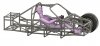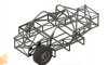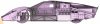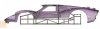
MK IV tubular spaceframe drawing

Nice thread to follow, note that Jac has not commented on the engine shown since you stuck a Ford in your drawings.:p
What country are you in? Your English is improving nicely as this thread moves along
Thank's for the compliment.
I live in Bavaria / Germany. Scratch building provides many challenges.
But honestly - Deepl.com is my friend
And you see Jac is back :)
 
You need more headroom. With the new helmets especially, you will be solidly up against the roof/roll cage structure. Not good.

Neil I have done a lot to get more space, but at some point you reach the limit. I extended the frame forward and moved the roll bar back as far as it would go.
All to get a more reclined position for more headroom.
My wife Britta says I should rather plan with the michelin man....
 

Attachments

  • frame1.JPG
    frame1.JPG
    136 KB · Views: 321
  • frame.JPG
    frame.JPG
    113.8 KB · Views: 319
  • sideview1.JPG
    sideview1.JPG
    134 KB · Views: 328
  • sideview.JPG
    sideview.JPG
    128 KB · Views: 347
Those are very nice CAD drawings. It looks to me as if you might be able to roll the top part of the 'cage rear hoop backwards 20-30 degrees to give you more space behind your head- space for a big helmet, HANS, etc. Driving with your neck bent forward and your helmet rattling off the rear bulkhead is not pleasant.
 
I already had this idea, too.
At the moment, the roll bar sits half under the Spider and half under the hood. If I put the roll bar at an angle, I have no support for the spider.
 
Hi - can someone maybe help me?
I am completely confused right now.
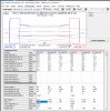
I have entered my chassis data into the Syspensions Analyzer, so far everything works.
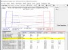
Now I have set static 20% AntiDive, that also works .
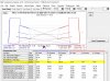
But if I compress the chassis 60 mm, then I get logical values for the left side (i think) , but for the right side something completely unrealistic is displayed.
Does anyone know what I'm doing wrong?
I have attached the data.
 

Attachments

  • 01_Suspension_Data.JPG
    01_Suspension_Data.JPG
    181.3 KB · Views: 317
  • 02_AntiDive_static.JPG
    02_AntiDive_static.JPG
    134.2 KB · Views: 317
  • 03_AntiDive_60mm_Dive.JPG
    03_AntiDive_60mm_Dive.JPG
    136.3 KB · Views: 326
Neil - I don't think so, only the camber is an input field,
the caster comes from the geometry.
For the static camber, I entered -1.5° on both sides so that both wheels point inward at the top.
Or do I understand you wrong?
It is very troublesome to work with the program, every time I open the file, half of the input data is missing again.
Unfortunately, I also get no answer when I ask the developer :(
 

Paul Hendrickx

Supporter
Hello,
did you try these one out?
found them helpful to make my suspension compromise decisions
Paul
 
Neil - I don't think so, only the camber is an input field,
the caster comes from the geometry.
For the static camber, I entered -1.5° on both sides so that both wheels point inward at the top.
Or do I understand you wrong?
It is very troublesome to work with the program, every time I open the file, half of the input data is missing again.
Unfortunately, I also get no answer when I ask the developer :(
I used that software (but maybe a different version) to design my suspension and I had no problems with it. My rear suspension is a 5-link type and the front is the common Mustang II a-arm setup.
 
I used that software (but maybe a different version) to design my suspension and I had no problems with it. My rear suspension is a 5-link type and the front is the common Mustang II a-arm setup.
This helps if your having software problems with suspension design.
 

Attachments

  • is (2).jpg
    is (2).jpg
    10.6 KB · Views: 283
Hello,
did you try these one out?
found them helpful to make my suspension compromise decisions
Paul
Thanks for the tip, I know the webseit.
Unfortunately, you can not work out anti-dive, anti-squat
 
Obviously, it depends on many things, including placement of main components, ride height, etc, but for my specific case; 4.5 inch front ride height and 5 in rear ride height with bottom of engine sump in line with plane of chassis bottom (no dry sump) then
front CoG: rear CoG
29.25​
cm
42.8​
cm
I did it the hard way by weighing/estimating most of the major components and calculating mass centres over the axle axes
 
Hi Trevor, Thank you very much!! So far I have calculated with 34 cm (estimated). That must have been a lot of work - thanks for releasing the info. It helps me a lot!
 
Back
Top